
Night mode range considerations
When the entire frame (or portions of it) appears dark, consider the maximum night mode range of each device model. For installations where the camera will view objects outside of its maximum night mode range, consider adding an 850nm infrared extender with a longer range.
Note: Reference the datasheet for more information on a certain camera model’s maximum night mode range.
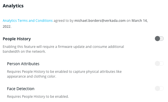
Disable analytics
Disabling analytics can improve night mode results. Analytics features reduce exposure time, which results in darker images.
 .
.
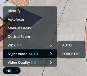
Disable night mode
If you would prefer to disable night mode entirely, you can change it to FORCE OFF.
Update Time Zone for a Camera
Update Time Zone for a Camera
Learn how to update a time zone for a designated Verkada camera
Updated over a week ago
The camera’s map location is used to determine the camera’s time zone. If a camera has incorrect time zone settings, ensure it is placed correctly on the map. The time zone is based on the location you set for the camera.
View the current time zone in Command
 icon.
icon.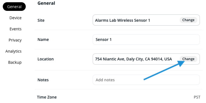
Troubleshooting Guide for CP52-E PTZ
Troubleshooting Guide for CP52-E PTZ
Learn how to troubleshoot Verkada’s CP52-E PTZ camera with WebRTC
Updated over a week ago
The CP52-E PTZ camera uses Web Real-Time Communications (WebRTC) to achieve ultra-low latency for both streaming and camera controls, from anywhere in the world. The expected latency should be around 0.5 seconds when the camera has properly established a WebRTC connection. However, there are some instances where the WebRTC connection might fail due to networking issues or firewall configurations.
Use this article to learn how to achieve the best performance and lowest latency for the CP52-E PTZ camera through the use of WebRTC.
Common questions
How do I know if WebRTC is not working?
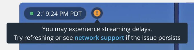
If you are experiencing a latency of around ~2 seconds, WebRTC has most likely failed. You will be able to easily determine this by looking at the video feed’s layover UI in Command. If you notice an orange exclamation mark (see image below) at the top of the CP52-E’s video feed, this indicates that the camera was unable to establish a WebRTC connection.
What are the recommended domains to use?
Verkada devices need to communicate with specific domains to provide you with a full-featured experience. For the CP52-E PTZ, the following domains must be accessible by the camera in order to establish a WebRTC connection:
*.control.verkada.com – TCP+UDP/443
*.pyramid.verkada.com – TCP+UDP/443
*.verkada.com – TCP+UDP/443
time.control.verkada.com – UDP/123
*:4100 – TCP/UDP on LAN (only required for local streaming)
*.kinesisvideo.us-west-2.amazonaws.com – TCP/443
*.kinesisvideo.us-west-2.amazonaws.com – UDP/443
*.us-west-2.compute.amazonaws.com – TCP/443
*.us-west-2.compute.amazonaws.com – UDP/443
See also Camera Network Settings.
Video resolution
| Model | Sensor Resolution | Streaming Settings |
| CP52-E | 5MP (2688 x 1944) | Static PTZ: 600–2500 Kbps
User-controlled PTZ: 2000–5000 Kbps Sentry Mode: 1500–4000 Kbps |
What if I still cannot establish a low-latency WebRTC connection?
If your network is configured properly as per the instructions above, and you still cannot establish a low-latency WebRTC connection
Troubleshoot Banding on Camera Feed
Troubleshoot Banding on Camera Feed
Learn how to troubleshoot a common video issue with Verkada indoor-installed cameras
Updated over a week ago
Fluorescent and high-frequency lighting doesn’t produce light in a steady manner compared to natural sunlight. Instead, these lighting sources pulse. For the human eye, this is not discernible as it appears as a steady light.
Cameras, however, utilize a rolling shutter, which means parts of the image are refreshed at different times. This causes the camera to show the variations in light caused by the pulsing characteristic of fluorescent and high-frequency lighting.
What is black banding?
The net effect appears as what’s called black banding across the camera’s feed. The power frequency from the mains power has a direct impact on the pulsing nature of these lights. Power frequency varies by location, which means that not all locations show black banding. For example, US utilizes 60Hz compared to Europe, which utilizes 50Hz.
What to do
If you see black banding on your camera, try to enable Wide Dynamic Range (WDR).
If that doesn’t work, contact Verkada Support. A Verkada Technical Support Engineer can assist you in removing the visibility of this banding on the camera’s feed by making the necessary changes to the camera’s configuration.
Troubleshooting Buffering and Latency
Troubleshooting Buffering and Latency
What to check when you’re dealing with buffering or latency on your cameras
Updated over a week ago
The expected delay when viewing footage should be ~2 seconds whether viewing in SQ or HQ. If you are seeing a delay greater than ~2 seconds review this article to make sure your network has the minimum bandwidth for our cameras to live stream.
Background
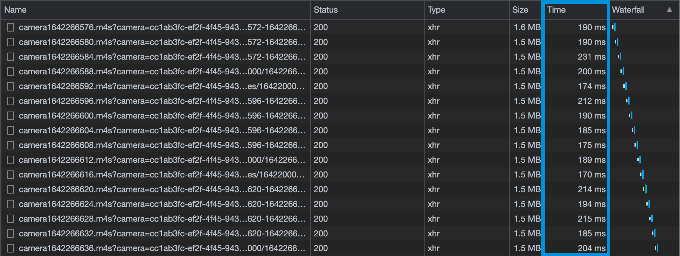
When you are looking at footage on your device, your browser needs to download the video files from the cloud. You can see these files being downloaded on the Network tab in your browser’s developer’s tools when you filter for “.m4s”:
Live View
.
Historical Footage
.
For a smooth stream, each video file needs to be downloaded in less than a second. Any longer will cause the video to not stream smoothly.
Causes of Buffering
There are two causes that result in camera streams buffering. Insufficient upload speed on the camera’s network and insufficient download speed on the viewer’s network. This causes the video files to downloaded slower.
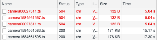
Notice that it took the browser longer than a second to download these files.
Identifying where the problem is
In order to figure out where the problem is, you will need to conduct a speed test on the camera’s LAN and the affected device’s LAN. You can do that by connecting a computer to the same LAN as the camera or the affected device and running a speed test on your preferred internet speed test website.
Fortunately, Google has a built-in speed test through their search engine:
.
Network Troubleshooting – Internet Sharing
Network Troubleshooting – Internet Sharing
A guide to network testing via a separate out-of-band path to the internet and how to take a packet capture via Wireshark
Updated over a week ago
There will be times when troubleshooting requires you to eliminate the core network as a source of problems. This guide will walk you through how to create a mini test-network using items you should have around the workplace.
Initial Setup
| Item | Number Needed |
| Mobile Hotspot | 1 |
| Laptop | 1 |
| PoE Injector | 1 |
| Short Patch Cable | 4 |
| Wireshark – Packet Capture software | 1 |
Daha fazla göster
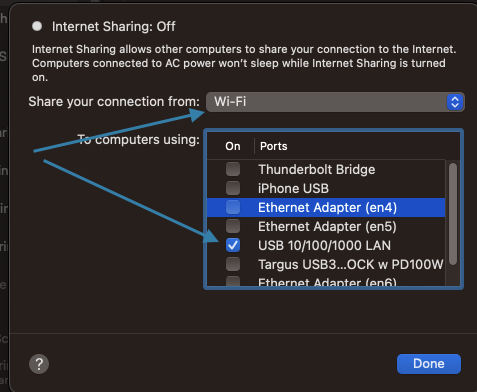
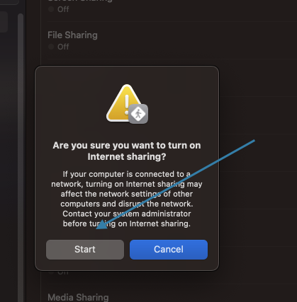
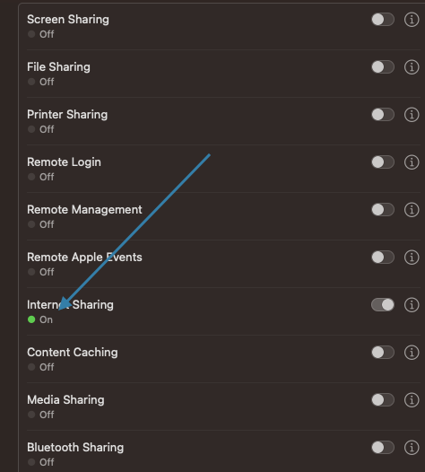
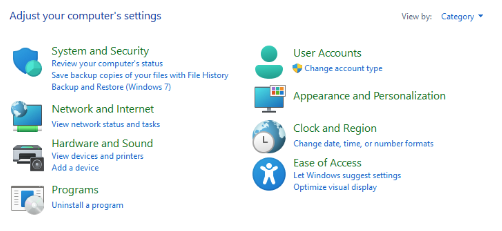
Setup for Apple Users

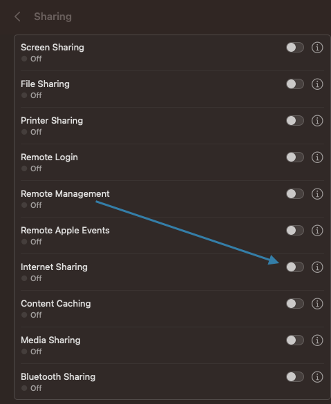
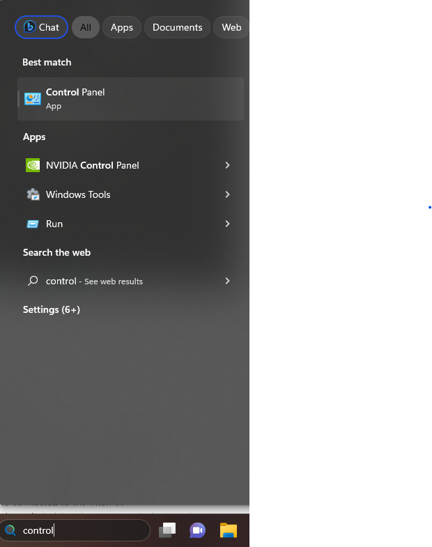
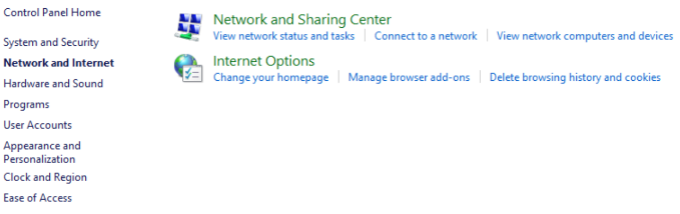
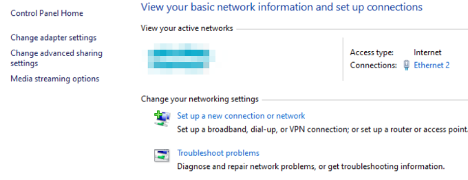
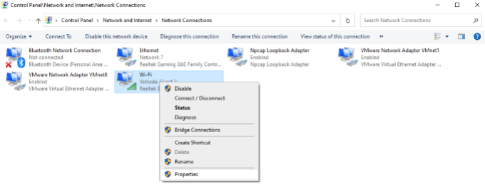
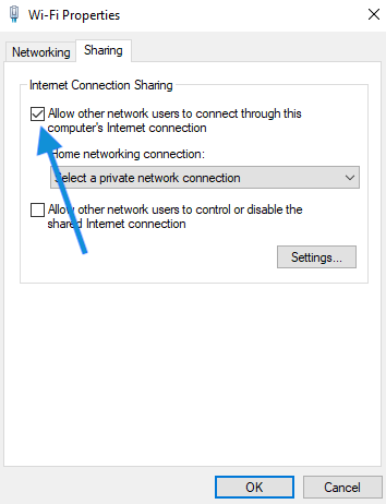
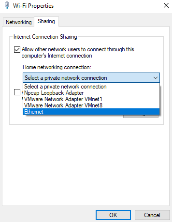
Setup for Windows ⊞
You may also like
About the author
M.Salih ASLAN
Hello, I live in Salih Turkey. I serve in dvr, nvr, security and surveillance industry. Write to me for any comments and suggestions ..
Add Comment