


Without a working BIOS, even the most powerful hardware can't be brought to life. In some rare cases, the BIOS chip in your system can become corrupt, which will return your system completely unusable. To fix this situation but also for other reasons like simply a backup, tuning, modding or enabling hidden features, flashing your BIOS ROM is interesting. Recently I got in the situation where the BIOS chip in my Lenovo X1 Yoga got corrupt. To fix this, I purchased the CH341a MiniProgrammer. In this post you can find the documented steps I took to reflash the BIOS and bring my laptop back to life.
As mentioned in the introduction, the BIOS chip from my Lenovo X1 Yoga laptop got corrupt and I managed to repair things by reflashing it with a working BIOS ROM. For this article, I will repeat the steps I took, on a Dell Precision T1700 MT. The process is exactly the same.
editor's note: the following explanation also applies to dvr or nvr recorders.
Youtube Video
If you are interested, I also created a YouTube video from this blogpost. If you prefer classic text, you can just follow the rest of this article:
Introduction
There are several ways to (re-)program the contents on your BIOS chip. The easiest is by running a BIOS update/programming tool directly on your working machine. The BIOS is mostly only used during the initial boot time and can safely be reflashed on a started system. Obviously, for that to work, the system still has to be able to boot. If this is no longer the case, you will need to reprogram the BIOS using another device.
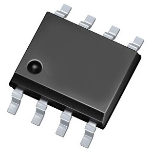
BIOS chips come in several different packages. Today, in my experience, most of the times, a SOIC-8 package is used. This is a soldered 8 pin (2×4) IC. This was the case for the Lenovo X1 yoga but also for the Dell Precision T1700 MT and some other systems I checked.
Hardware requirements
1) Programmer
In order to read and write the contents on our BIOS chip, we will need a programmer that can physically connect with it and perform those actions.
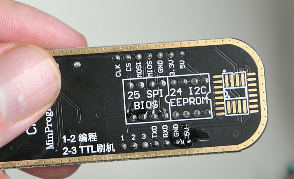
There are a lot of different types of programmers out there but a popular model, most likely due it's wide availability for low prices on Ebay, Amazon or Aliexpress, is the CH341a MiniProgrammer:
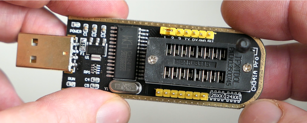
This device allows a variety of options to program/flash SPI flash or BIOS chips but also other types of EEPROMs of type 24XX and 25XX which are found in various devices like routers, access points, videocards,… and is suited to program the SOIC-8 BIOS chips that are used in a lot of systems these days.
2) Adapter, cable or clip
In case your BIOS chip is socketed, you can remove the chip from the board and place it on top of the programmer (with an adapter). If it's soldered on the board you will either need to de-solder it or use a clamp/clip that fits the package type of your BIOS chip.
Although desoldering this type of IC is not very hard, it's still a lot easier to use a clip that is suited for the package type. This avoids the need to remove the chip from the motherboard and the risk to potentially damage other components.
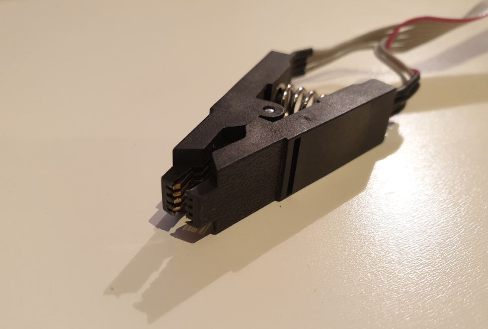
The clip, as you can see above, can be placed on top of the chip on the board. When doing so, you need to carefully pay attention that the red wire, indicating pin 1, matches with the side of the IC that has a small dot, indicating pin 1 on chip side.
The rest of the connections should follow the same rule. On the CH341a MiniProgrammer, there is also an indication to where pin 1 should be inserted. As you can see, this is more towards the middle: top row, 4th pin from left to right, of the pin layout for a SPI/BIOS chip (type 25).
While connecting the IC to the programmer, make sure the motherboard is powerless and the programmer is not connected to USB either as this could potentially corrupt/erase or even break the BIOS chip.
3) Locate the BIOS chip on the motherboard
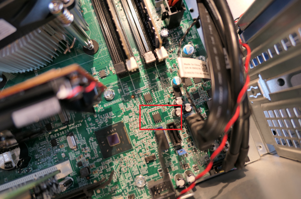
The location of the BIOS chip on the motherboard is not always very clear. By searching for ICs that look like a SOIC-8 chip, you can already eliminate a lot. If you're lucky it has a nearby label like BIOS or SPI. Also, I noticed that in most cases it is not too far from the CMOS battery. Unfortunately there is no fixed rule. You probably will need to search a bit or put your hopes on mighty Google to find someone else that already went through the same exercise.
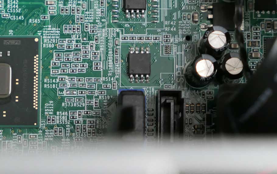
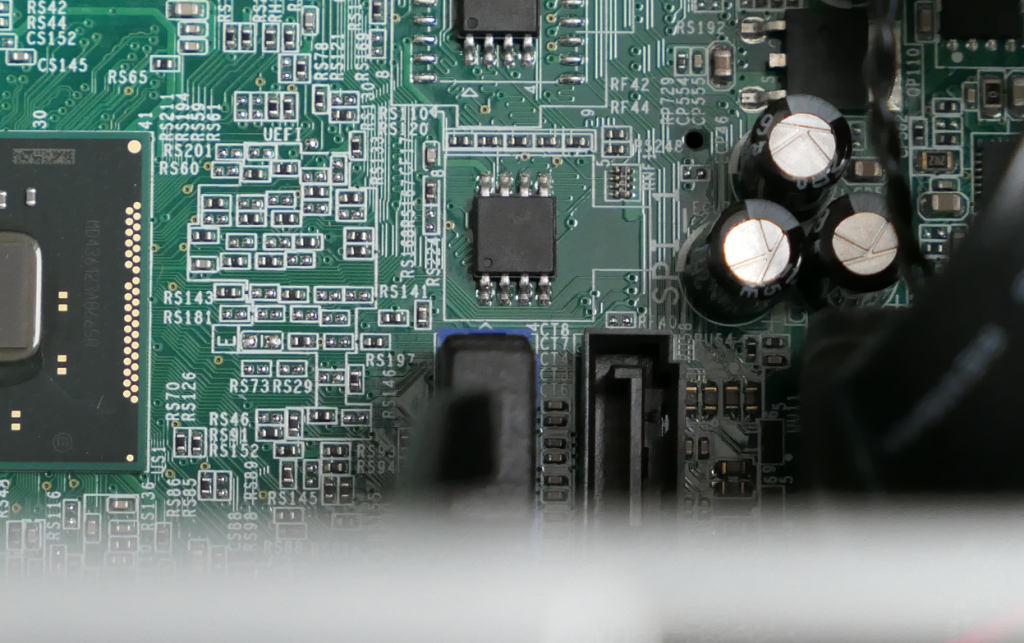
For the Dell system, I found the BIOS chip on the lower right part of the motherboard, next to a label “SPI”:
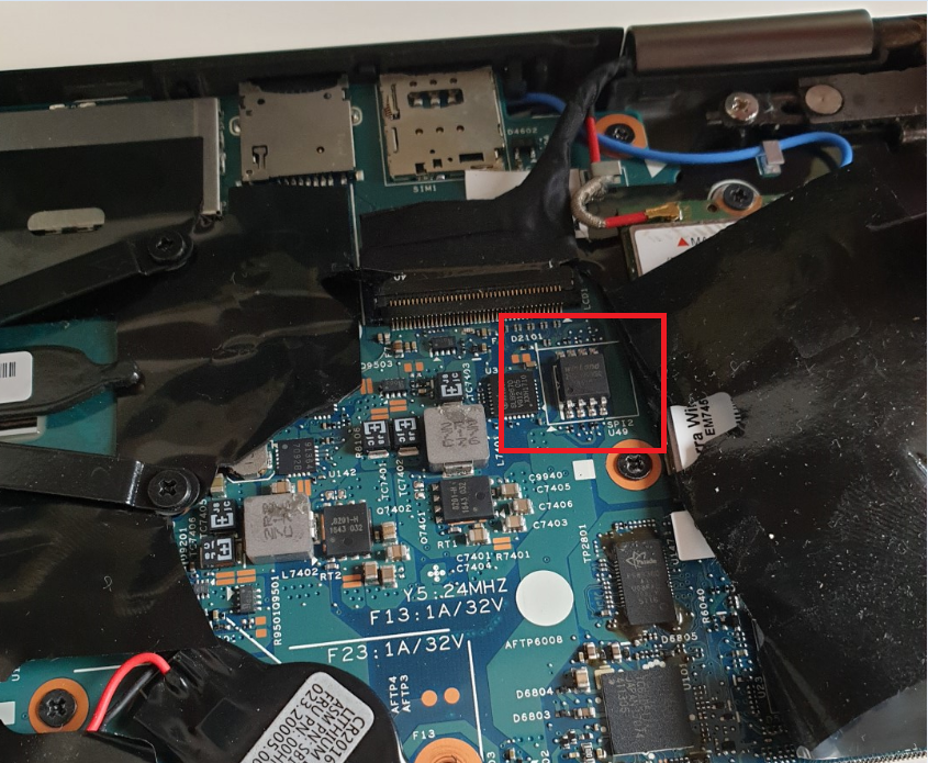
For my Lenovo X1 Yoga, it was harder to find as the laptop has a plastic foil covering the internal components and I didn't want to completely remove it. It turned out to be located near the cellular modem, under the connector for the screen:
4) Identify BIOS chip type
The programmer is not always able to detect the exact chip type. To make sure, you will need to read the physical label on the chip itself or make sure to look up which exact type is used in your system.
For the Dell system I used, the text was pretty readable by taking a proper macro picture and zooming in:
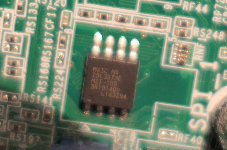
The label is among the detected types: MX25L3273E.
For the Lenovo X1 Yoga, I was not able to read the label as it got washed out somehow. All I could see was the Winbond label. After a quick Google search I found that for that device, the SPI type was W25Q128FV.
Software requirements
Windows
For Windows, you will need a tool to read and write the contents of the BIOS flash chip. For this post, I used AsProgrammer which you can download from here: https://github.com/nofeletru/UsbAsp-flash/releases/
There are probably other working tools but I found this one to give the best results with the CH341a. Drivers were not needed for the programmer. It just worked when connecting it to USB on Windows 10.
Linux
For Linux, similar as in Windows, you will need a tool to read/write to the SPI. Here I used flashrom which is part of most distributions' repositories. Same as for Windows, no additional kernel modules were needed to recognize and use the CH341a on my system.
You can easily install flashrom using your package manager.
For example for Debian 10:
jensd@deb10:~$ sudo apt install flashom
Reading package lists… Done
Building dependency tree
Reading state information… Done
…
BIOS chip programming
For both Windows and Linux, the same sequence of steps can be following:
- Connect the clip to the BIOS chip, nothing should be powered
- Connect the clip or adapters to the CH341a programmer
- Connect the CH341a programmer to USB.
I recommend using an extension cable instead of putting it directly in your USB port. - Start the tool to program (AsProgrammer for Windows, flashrom for Linux)
- Make sure you configure the correct type of programmer and BIOS chip
- Read the data from the chip twice and save it to a file each time
- Verify the checksum of both files
This is to make sure that there is no corruption when reading data from the chip. As reading in this condition could brick/corrupt it. - Write the correct/modified file to the chip
- Optionally perform another read and verify the checksum of this with the written file to make sure the contents matches with what you flashed in it.
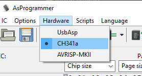
Programming under Windows
We start with step 5 as explained above. After starting AsProgrammer we first need to set it to use a CH341a. This can be done in the hardware menu:
Next. we can click the icon to detect the chip type:
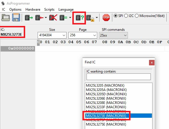
As mentioned above, the programmer is not always able to detect the exact type and gives you a list of possible options. We identified the Dell BIOS chip as type MX25L3273E so we can select this from the list here.
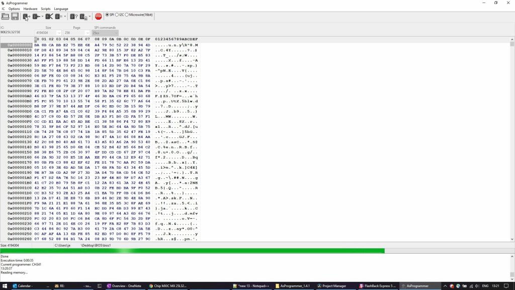
Next, step 6, we can read the data from the chip by clicking the icon with the green arrow. Once reading is completed, save the output to a file by clicking on the save (disk) icon.
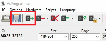
It's important to repeat this step twice as we need to make sure that communication with the IC is working as expected:
After completing and saving the second dump of the BIOS, we can compare the two files to see if they are exactly the same. This is step 7. We can do that easily by calculating the MD5 checksum from them. In Windows this can be done using certutil with the following command:
Microsoft Windows [Version 10.0.18363.1256]
(c) 2019 Microsoft Corporation. All rights reserved.

C:\Users\jensd>cd c:\data\BIOS

c:\data\BIOS>certutil -hashfile bios1 md5
MD5 hash of bios1:
83bcd273cf7a5fd9a1075b823c83a0e2
CertUtil: -hashfile command completed successfully.

c:\data\BIOS>certutil -hashfile bios2 md5
MD5 hash of bios2:
83bcd273cf7a5fd9a1075b823c83a0e2
CertUtil: -hashfile command completed successfully.
In the above output we can see that both files generated the same hash, so they are identical. This is a good indication that communication with the IC and programmer works as expected.
Both files can now be saved as a backup in case things go wrong of in case you want to reflash the BIOS to an older version.
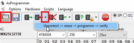
Next, we can finally write the new or modified contents to the BIOS chip. This can be done by first opening a rom file in AsProgrammer, using the open button, then clicking the down arrow next to the write button and choosing Unprotect -> erase -> programm -> verify:
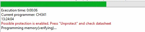
You can follow the progress and status in the bottom of the window:
Once programming is done, optionally, you can read the BIOS chip again, as indicated above, and compare the hash of the written file with the actual contents after writing. This is to make sure that there is no corruption and the contents of the chip matches exactly with the data you wanted to be there.
Programming under Linux
The steps under Linux are the same as from Windows. Only here we will use the CLI tool flashrom. As on Windows, we need to go through step 5 and set the correct programmer and BIOS type. The easiest is to launch the tool and let it try to detect the type of BIOS chip:
jensd@deb10:~$ sudo flashrom --programmer ch341a_spi -r backup1.bin
flashrom  on Linux 4.19.0-13-amd64 (x86_64)
flashrom is free software, get the source code at https://flashrom.org

Using clock_gettime for delay loops (clk_id: 1, resolution: 1ns).
Found Macronix flash chip "MX25L3205(A)" (4096 kB, SPI) on ch341a_spi.
Found Macronix flash chip "MX25L3205D/MX25L3208D" (4096 kB, SPI) on ch341a_spi.
Found Macronix flash chip "MX25L3206E/MX25L3208E" (4096 kB, SPI) on ch341a_spi.
Found Macronix flash chip "MX25L3273E" (4096 kB, SPI) on ch341a_spi.
Multiple flash chip definitions match the detected chip(s): "MX25L3205(A)", "MX25L3205D/MX25L3208D", "MX25L3206E/MX25L3208E", "MX25L3273E"
Please specify which chip definition to use with the -c  option.
Same as with AsProgrammer, we can see that flashrom is able to come up with a selection but we still have to specify the exact type using the -c option. As our type is MX25L3273E, we can now read the contents of the chip and save it to file backup1.bin using the following command:
jensd@deb10:~$ sudo flashrom --programmer ch341a_spi -r backup1.bin -c "MX25L3273E"
flashrom  on Linux 4.19.0-13-amd64 (x86_64)
flashrom is free software, get the source code at https://flashrom.org

Using clock_gettime for delay loops (clk_id: 1, resolution: 1ns).
Found Macronix flash chip "MX25L3273E" (4096 kB, SPI) on ch341a_spi.
Reading flash... done.
jensd@deb10:~$ sudo flashrom --programmer ch341a_spi -r backup2.bin -c "MX25L3273E"
flashrom  on Linux 4.19.0-13-amd64 (x86_64)
flashrom is free software, get the source code at https://flashrom.org

Using clock_gettime for delay loops (clk_id: 1, resolution: 1ns).
Found Macronix flash chip "MX25L3273E" (4096 kB, SPI) on ch341a_spi.
Reading flash... done.
Same here again is to read the contents twice and save it in two different files. Once done, it's time for step 7 and we can compare the checksum of the files to see if they are matching:
jensd@deb10:~$ md5sum backup1.bin
83bcd273cf7a5fd9a1075b823c83a0e2  backup1.bin
jensd@deb10:~$ md5sum backup2.bin
83bcd273cf7a5fd9a1075b823c83a0e2  backup2.bin
Like on Windows, using this method we can be sure that the programmer can communicate properly with the chip and we reduce the chance for corruption. All seems to be good in the above output. If you see a different hash, you first need to fix this before proceeding.
backup1.bin and backup2.bin can be saved for later as they are a proper backup of the current contents of you BIOS chip.
The next step is to write the backup, dump or modded file using flashrom. This time we use the -w option and specify the input file:
jensd@deb10:~$ sudo flashrom --programmer ch341a_spi -w bios.bin -c "MX25L3273E"
flashrom  on Linux 4.19.0-13-amd64 (x86_64)
flashrom is free software, get the source code at https://flashrom.org

Using clock_gettime for delay loops (clk_id: 1, resolution: 1ns).
Found Macronix flash chip "MX25L3273E" (4096 kB, SPI) on ch341a_spi.
Reading old flash chip contents... done.
Erasing and writing flash chip...
Warning: Chip content is identical to the requested image.
Erase/write done.
Optionally here as well is to read the contents again and to compare the MD5 checksum with the file we used as input (bios.bin).
In the example above, I wrote back the earlier backed up file, so flashrom was smart enough to detect this and give me a warning about it.
Hopefully this article can help some people that, just like I was, feel bad because their expensive piece of hardware completely stopped working just because the contents of one tiny IC got corrupted.


It really worked, I appreciate it!
I can’t upload
please provide support for me i leave my email address
Can you write your contact number?
I sent an e-mail from the communication channel. Can you help?
I really love you
I really love you
It was a great sharing
It was a great sharing
I can’t upload
hi how can i do
problem not solved thanks
hello nice sharing thanks
I really love you
my recorder is not working
I sent an e-mail from the communication channel. Can you help?
problem not solved thanks
I sent an e-mail from the communication channel. Can you help?
problem not solved thanks
I really love you
I sent an e-mail from the communication channel. Can you help?
I am having trouble with the installation
I am having trouble with the installation
I can’t upload
Can you write your contact number?
hello nice sharing thanks
It really worked, I appreciate it!