ClareVision NVR and Camera General Guides
The following guide gives you the basics on getting started with ClareVision NVRs and Camera setup.
Overview
The following article provide the following information:
- The basic functions of an NVR
- The basic functions of an IP camera
- Best practices for setting up an NVR
NVR’s
The NVR provides two basic functions: it network attaches the cameras and provides storage. In fact, the NVR does very little else.
- Network services: the NVR provides a central place to access IP cameras. You can attach IP cameras directly to the ports of the NVR or leave the cameras on the LAN. The NVR can be configured attach to those cameras for purposes of centralized access and recording .Centralized access can be viewing on the web console or providing access to integrated solutions such as the ClareOne Panel or a home automation system such as Control4
- Recording services: the NVR also provides recording services. You may record full time video or motion events, smart events, alarm events or any combination.
Note:
The NVR does NOT create events. The camera creates all events and the NVR simply records them. Why are the settings in the NVR for motion events, smart events and alarm events? Convenience. The NVR is simply configuring the camera so you do not have to log into each camera to configure an event. Check it out: configure an event in the NVR and log into the camera. You will see the exact settings you configured in the NVR in the camera settings web console.
ClareVision NVR and Camera General Guides
Read Next : Hikvision Hik-Connect complete setup guide
Tip:
Since many ClareVision cameras come with SD cards installed, when should I use an NVR?
- Full time recording: the SD Cards are not useful for full time recording. A 4MP camera will overwrite in less than one day on full time record
- Storing multiple event types: the camera will store motion OR smart events OR alarm events. Use the NVR if you need multiple event types stored
- Camera count: if you are getting above 2 to 3 cameras, it is probably time for an NVR. Centralized access and storage flexibility will be very useful in those use cases.
Note:
A word about ports on the NVR. Ports and channels often get used interchangeably. For Clare Controls, an NVR port is a PoE port on the back of the NVR. Each port is a “physical channel”. For example, an eight channel NVR has 8 physical channels or ports. A virtual channel is a channel that is connected to the NVR via the LAN port, not a PoE port. Therefore, a channel is a connection between the NVR and a camera whether physically on a port or virtually via the LAN. The following table details the channel count by model number for ClareVision NVR’s:
| Model | Physical Channels | Virtual Channels | Total Channels |
| CLR-V200-4PNVR1 | 4 | 5 | 9 |
| CLR-V200-8PNVR2 | 8 | 8 | 16 |
| CLR-V200-16PNVR4 | 16 | 9 | 25 |
IP Cameras
The IP camera is where almost everything interesting happens. The IP camera collects, analyzes and forwards video streams and snapshots to one or more clients. The camera can provide service to a mobile app, the NVR and an integrated control system simultaneously. It also provides multiple streams of video in different resolutions and frame rates so the client device can select the stream it can process. The following provides a high level reference highlighting the differences between the Value Series and Performance Series ClareVision IP cameras:
| Feature | Value Series | Performance Series |
| Motion | ✔️ | ✔️ |
| Advanced Motion | ✔️ | |
| Smart Events | ✔️ | |
| Streams | 2 | 3 |
| Starlight | ✔️ | |
| Available Varifocal | ✔️ | |
| Fixed Lens | 3.6mm | 2.8mm |
| Color at Night | Coming Soon |
In summary, the camera is where everything interesting happens. The NVR simply provides convenient access and storage.
Next, let’s set up an NVR with ClareVision and ONVIF cameras…
Setup a ClareVision NVR and IP Cameras
What You Need
Learning by doing is far better than reading articles and watching videos. Before you proceed, you will need the following:
- ClareVision IP camera: we will use a Performance series camera in our exercises.
- ClareVision NVR
- A computer with internet access
- A mobile phone with ClareVision installed. (Do not install ClareVision Plus – that is our legacy app)
- A wired connection to your LAN
- An 8 port PoE switch (you will not leave this at the job site)
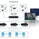
Step One: Install the NVR on Your LAN
The following image shows the connection scheme for an ethernet switch connected to an NVR and camera.
Tip:
If you are using an ethernet switch or router with a built in switch, the switch port will have LED’s indicating connection status. One of the LED’s will be the link light. The link light indicates whether data is being transmitted to the NVR. The link light will often flash.
If your link light is flashing on the ethernet switch you are passing data to the NVR. Success!
Step Two: Find the NVR on Your LAN
All ClareVision NVR’s ship with DHCP turned on. DHCP simply means the router will assign an IP address to the camera when it boots up using the LAN IP address scheme. Example:
- Router IP Address: 192.168.1.1 (typical)
- IP address range that may be available: 192.168.1.2 through 192.168.1.255
- Router will assign an address like this: 192.168.1.x, where x can be any number between 2 and 255.
How do you find your NVR so you can login and configure? Download the IP search tool here.
Install and Launch IP Search and select “Search”

All IP cameras and NVR’s regardless of their IP address will appear in the results window. The model numbers will appear as well so you know which one is an NVR.
Next launch a web browser (Chrome or Edge) and enter the IP address of the camera you just installed.
The default USERID is: admin (not case sensitive)
The default password is the first six characters of the UUID. The UUID can be found on the NVR label or the quick start guide.
Step Three: Download the Plugin
The NVR’s and cameras support Chromium browsers. We test on Microsoft Edge and Google Chrome. The plugin dramatically improves video performance vs. browsers without a plugin.
Note:
The plugin for the NVR is different than the camera plugin.
NVR plugin: LsNXVRPlugin.EXE
Camera plugin: LSIPCPlugin.EXE
The plugins can be downloaded directly from the web interface of any camera or NVR
See the upper right corners of the NVR web user interface
Step Four: Update the NVR to the Latest Firmware Release
Clare Controls releases NVR firmware with new features about once every four months. Chances are, your NVR will need to be updated when you take out of the box. There are two ways to update the NVR firmware.
You can go to the NVR firmware database is located here and download the firmware file. You then select manual upgrade by selecting the Configuration tab, Maintenance/Manual Upgrade
OR
Log into the NVR and go to the Configuration tab and click on Maintenance/Online Upgrade to review the firmware version.
Click on “Check”. The NVR will go to our OTA servers and check for an upgrade. If one is available you will be prompted to accept the upgrade. You should always accept.
Go HERE for a guide to quickly updating the firmware on your cameras
Next, we will add cameras to the NVR. We will break this down into three steps:
- Adding ClareVision cameras to the NVR by attaching to the NVR physical channels
- Adding ClareVision cameras to the NVR by attaching them to the NVR virtual channels on the LAN
- Adding ONVIF cameras to the NVR (Luma, ClareVision Plus/Legacy, Hikvision etc)
Step Five: Add ClareVision Cameras to the PoE Ports
Attach the camera to the NVR physical PoE port. This connection must be direct and cannot be routed through an ethernet switch on the way to the PoE port. Once connected, wait until the two LED’s on the NVR are illuminated.
The green LED is the PoE power indicator. If it is lit, the NVR is supplying power to the camera. The amber LED is the link light. When this is flashing, the NVR is communicating with the camera.
Now simply wait a couple of minutes…..
Go to the Live View tab and click on the left side of the icon next to the channel number to which you connected the camera. A small green indicator will light up just to the left of the “C” in the word channel. The camera video should show up in the appropriate tile. In the example below, the camera is connected to physical channel one and shows up in tile number one on the Live View Screen.
What just happened?
The NVR powered the camera and the camera booted up. Upon boot-up the NVR discovered the Clare Camera, added it to the channel list based on the port number to which it was attached, the NVR assigned the camera a static IP address based on the NVR’s private IP subnet and changed the camera UserID and password to match the NVR admin UserID and password. That is Plug-n-Play.
You can continue adding cameras to the physical channels of the NVR and all will behave as noted above.
Step Six: Add ClareVision Cameras to the Virtual Channels (on the LAN)
Let’s assume you had no way to physically route a wire back to the NVR, but wanted the camera on the NVR. No problem – you are now going to add the camera to a ‘virtual channel’ on the NVR.
To do so, go to the Configuration tab, Channel/Camera.
This NVR is the CLR-V200-8PNVR2, 8 channel NVR. Notice it has 10 cameras on it. To discover new cameras, click on the “Add” button.
What just happened?
Based on the selection in the dropdown box in the upper right corner, the NVR just scanned all physical ports and the LAN for any ClareVision (private) and ONVIF cameras. It found two that were not on the NVR prior to the scan.
If a camera shows up as private and you click in the white box on the left side of the row, and click “Add”. The camera will be added exactly the same way it would have been added had it been on a PoE port – Plug-n-Play.
That is really all there is to adding ClareVision cameras to a ClareVision NVR.
Step Seven: Adding ONVIF cameras to a ClareVision NVR.
Let’s assume the ONVIF camera is on the general LAN like in step six above. Follow the exact same procedure as in step six, plus the following:
In the channel screen below, click on the edit link in for the ONVIF camera you just added
The following screen will pop up:
Enter the ONVIF UserID and Password for the discovered camera, click “OK”.
Note:
ONVIF must be enabled in the camera being attached to the ClareVision NVR. The NVR uses WS-Discovery to find ONVIF cameras. If ONVIF is not enabled the NVR will not discover the camera. Several Hikvision models require and ONVIF user to be enabled to allow connection to the camera via ONVIF. Consult your installation manual for the camera you are trying to attach to the ClareVision NVR if it does not discover for additional details.
This ARTICLE details adding an ONVIF camera to a PoE port on the NVR. The process is slightly different than detailed above.
Step Eight: Aligning Connections to Channels on Your NVR
The NVR will assign channels based on either the physical connection (PoE port 1, 2 etc) or based on the order in which they were attached for virtual channels. The first camera added to the NVR on the general LAN will be assigned to channel 9, the second to channel 10 etc.
Let’s say you had 10 cameras, but only ONE on a physical channel / PoE port. The Live View screen would show a camera in tile 4 since that is where it was attached. The next 8 cameras would automatically be assigned to ports 9 through 16.
Two problems – what about the 10th camera and the NVR Live View Screen would be very awkward showing one camera on tile 4 and 8 cameras on tile 9-16.
This where PoE bonding configuration becomes very handy.
PoE bonding allows you to decouple the logical connection between a physical channel and a channel number. In the example above, all channels besides channel 4 are unbonded from the physical ports. This makes 7 of the first nine channels available for virtual channel assignments.
Two problems just got solved:
- We now have enough channels for the 9th camera located on the LAN
- The channel assignments are now 1-10 making the NVR preview interface very organized.
It was the un-bonding process that allowed the channel list to appear as orderly as it did in the above example.
Caution:
The channel list is very important to get organized up front before you start configuring cameras and recording schedules. Get your list sequential and in the order in which you want channels to appear in the Live View screen before you do anything else. You can see in the edit screen shown above the channel number is configurable. Do all of this organization before you start setting up recording, integrating to ClareOne, Control4 or setting up the mobile app.
If you get the channel list twisted up and want to start over, you can default the camera list alone by going to the Configuration tab Maintenance/Default
Click on the “Camera” button and the channel list will be wiped. You can start over.
Step Nine: Setting up Events on Your Cameras
Now that your cameras are solidly on the NVR, it is time to set up motion and smart events for all of your cameras. The good news is you can do all of that from the NVR interface.
Note:
Remember, the NVR does not analyze video or create events, the cameras do that. When you access the NVR menu to configure an event such as motion, you are really just using the NVR to configure the camera.
The only thing you configure on the NVR that is actually an NVR setting is the recording schedule.
Go to the Configure tab and select System/Motion Event or System/Smart Event. In the following example, System/Motion Event was selected
This configuration screen is extremely similar to the native camera configuration screen. If you make changes here to the motion grid layout for example and log into the camera, you will see the changes you made from the NVR web UI.
Warning:
You must have the Channel Recording option selected AND the event enabled for the camera channel to record and send push notifications. The Channel Recording box is selected by default from the factory. Do not deselect it.
The drop down menus for channel selection are smart and will only show you the channels that have cameras that support that event type.
As an example, although this NVR has 10 cameras on it, only 5 support smart events.
See this article for motion detection setup.
See this article for smart event setup.
Although those articles are written referencing the camera web user interface, they are extremely similar on the NVR.
The recommendations related to Event Arming vs. Record Schedule apply to the NVR setup as well.
Caution:
It is easy to get confused by the multiple calendars that are in a camera or NVR. The event arming schedule shown above is the primary calendar you need to manage.
If your installation requires events to be disabled during certain hours of the day or days of the week ALWAYS do the following:
1. Use the event arming schedule to control when the event will be analyzed and propagated
2. Leave the record schedule on 7×24 record. DO NOT try to match the two calendars – use the event arm schedule to control when events happen NOT the record schedule.
Let’s move on to recording!
Step Ten: Setting up Recording on Your NVR
The primary difference, other than capacity, between camera based recording and NVR based recording is the NVR can record all event types and full time record simultaneously while the camera can only record one event type to the SD card.
Recording schedules are setup under the Configuration Tab Storage/Recording Schedule.
You can record any one or all of: normal (full time), motion, alarm, motion and alarm and smart events (intelligent).
Warning:
You must check the enable box for any recording to happen on the selected channel.
At the risk of being completely redundant, if you are arming an event such as motion or smart events you should set the recording to 7×24 and use the event arming schedule to control when the camera will propagate that event type. Doing so will ensure the user will always have an event to look at in the event log of the mobile app when a push notification is sent.
To change a recording parameter, just click on a line and the following will pop up:
Lastly, “More Settings” is where you will find pre-record and post-record settings.
Step Eleven: Directly Accessing Your Cameras that are on the Physical Channels
The cameras that are on the physical channels will not show up on an IP scan and are not accessible on the general LAN.
Note:
The four channel NVR does expose the cameras on an IP Search scan, but are not accessible from a browser interface on the general LAN. The 8 and 16 channel NVR’s do not expose the physical ports at all.
Enter the Virtual Host. You can access any camera, whether on the Virtual Channel or a Physical Channel (PoE Port) using the Virtual Host.
Go to the Configuration tab, Channel/Camera:
Click on the IP address in the right column and you will be taken to a login screen for that camera:
Notice the IP address is really the NVR with a port number. From this screen you can log into the camera, check settings, configure local record and manage firmware updates. You are accessing the camera directly.
Tip:
When integrating ClareVision cameras to control systems such as Control4, use the ClareVision Camera driver, not the NVR driver. The IP address you use is the NVR IP address with the associated port number as shown above. When you integrate that way, you are using the NVR to proxy access to the camera, but using an ONVIF driver to access video streams, snapshots, motion events and smart events. You can create push notifications and/or rules in the Control4 automation system based on events in the camera when you integrate in this fashion. (Events are not available in the NVR driver)
Use the NVR UserID and password, and we are in!
Step 12: Adding the NVR to the ClareVision Mobile App
Now that you have set up your NVR, it is time to add it to the ClareVision app. It is quite simple.
Launch the ClareVision App
Tap the ‘Plus’ sign and you will be presented the following options:
Selecting NVR will cause the app to bring up a different user interface than it does for an individual camera
Tap the NVR Icon and you will be presented with the three options shown below.
If you tap device is on the network, the app will scan the LAN for any ClareVision cameras or NVR’s and present them in the following screen. Device is on a remote network provides you with the option of scanning a QR code for a camera on a remote network. The system will locate it anywhere in the world and provide you with a login screen to add the remote camera or NVR.
In our example, we tapped on “Device is on the local network” and two devices were found.
Tapping on a device brings you to a login screen where you may enter the credentials
And DONE!
You just successfully installed, configured and enabled a ClareVision NVR with ClareVision cameras on and off the physical ports as well as adding an ONVIF camera. We then connected the NVR to the ClareVision mobile app. Push notifications and events as configured will automatically propagate to your customer’s mobile device!
Closing:
This was not an attempt to explain in great detail every option/setting/configuration in the NVR. Rather this article was intended to give you a simple step by step guide to setting up and NVR with cameras in multiple configurations from multiple manufacturers. If you follow the steps in the order detailed you will win more than you lose.
This article will walk you through the details on adding an ONVIF camera to a physical port/channel on a ClareVision NVR
Overview
This article will provide you with the information needed to add an ONVIF camera to a ClareVision NVR.
ClareVision NVR’s are ONVIF S/T compliant as a client whereas the cameras are ONVIF S/T compliant as devices. ONVIF compliance implies ClareVision NVR’s will enable discovery, receive and record streams, snapshots and motion events from ONVIF compliant devices.
Background on Discovery and Attachment
ONVIF uses a multicast method called WS-DISCOVERY. In essence the NVR sends out a multicast message to the network. All ONVIF devices listen for that multicast message to respond with information required to address the camera on the network. Remember, multicast discovery DOES NOT USE the IP address of the device it uses a multicast IP address. Here are a few things WS-DISCOVERY does not do:
- It does not modify or change the IP address of the discovered device
- It does not modify or change the UserID of the discovered device
- It does not modify or change the password of the discovered device.
What does this mean in practice?
ClareVision NVR’s can discover ONVIF cameras anywhere on the LAN or on the physical channels of the NVR and display the existence, model number and IP address of the discovered device in the channel list. It DOES NOT mean it can communicate with it. Here are few facts to consider using Luma as an example (applies to any ONVIF camera):
- Out of the box, a Luma camera has a static IP address of xxx.xxx.xxx. If the camera is on your local domain and your local domain has a different address scheme the router will route exactly zero messages between the ClareVision NVR and the Luma camera.
- There is no discovery method in ONVIF to transmit UserID’s and passwords, so even if the Luma camera is on the same domain as your NVR, the NVR will not auto-discover the UserID or password.
- If the Luma camera is on the physical port of the NVR, it will not be on the private domain of the ClareVision NVR (default 192.168.11.xxx). As a consequence, the NVR will not communicate with the Luma camera at all.
Attachment and Discovery Summary
| Device Type | Camera on LAN or Local Ports | Discovery | Auto-Change IP Address | Auto Assign UID and PW |
| ClareVision | Local | Auto | Yes | Yes |
| ClareVision | LAN | Auto | No, IP address change is not required | Yes |
| ONVIF | Local | Manual | IP address must be changed | No |
| ONVIF | LAN | Auto | No, IP address change is not required | No |
Attaching a Luma or ONVIF Camera to a ClareVision NVR on a Physical Port
Step One: Initialize the camera and set the UserID and Password
Refer to you Luma or ONVIF camera user guide for UserID and setup.
Note:
Some ONVIF cameras do not have ONVIF turned on by default. Consult your user manual to determine the default status of ONVIF on the device and ensure it is active and the UserID and Password for that user on the device is known. For example, some Hikvision cameras require you to set up a specific ONVIF user while others do not.
Step Two: Set the Device IP Address to the Domain of the ClareVision NVR
The ClareVision NVR private domain is defaulted to 192.168.11.xxx. That default can be changed under the Configuration tab, System/Network:
The bottom cell – Internal Net Card IP sets the private domain.
Make sure your ONVIF camera is on your general LAN and go to your network settings on your ONVIF camera and set the network settings as follows:
DHCP: disabled
IP address: 192.168.11.xxx, where XXX can be any address between 3 and 255. We recommend starting assignments at 26 to stay out of the range of the NVR’s aut0-assignment range.
Step Three: Move the Camera to the Physical Port of the NVR and Use Manual Add
Once you set the IP address as required, you will not longer be able to log into the camera on your general LAN. Move the camera to any physical port of the NVR and let the camera boot up.
To to the Configuration tab, Channel/Camera
Hit “Manual Add”
You must select the channel, enter the UserID and password, the IP address and the port number. Once complete, hit “Save”
That’s it, you just added and ONVIF camera to a physical port of the NVR. Using ONVIF, the NVR will allow you to configure motion events, schedule recording of motion or full time recording. You can use the NVR driver or the camera driver via the Virtual Host as you can with ClareVision cameras and the live view, snap shots and events will all propagate to the ClareVision mobile app.
You can view the entire setup process in the videos below.
Setting up Hikvision/ONVIF Cameras connected to a ClareVision NVR:
Setting up networked Hikvision/ONVIF cameras to work with a ClareVision NVR:
Note:
Notice in the protocol column that your ONVIF camera listed ONVIF and the ClareVision camera listed Private. It is the Private Protocol that allows cameras and NVR’s from the same manufacturer to exchange information and settings without manual intervention. The ClareVision Private Protocol, upon discovery, will change the IP address of the camera if on a physical port and assign the NVR UserID and password to the camera which is what provides the Plug-n-Play feature set.
We’re guiding you step-by-step on how to configure ClareVision cameras to work with a ClareVision NVR. This includes cameras that are plugged directly into the NVR using the POE ports or cameras which are found on the network.
Related Article:
Video: How to set up a ClareVision NVR.
This setup process is the same for all ClareVision NVRs:
CLR-V200-4PNVR1
CLR-V200-8PNVR2
CLR-V200-16PNVR4
In this video, we cover how to set up ClareVision NVRs. To download the IP Search Tool, please visit our page HERE.
This setup process is the same for all ClareVision NVRs:
CLR-V200-4PNVR1
CLR-V200-8PNVR2
CLR-V200-16PNVR4
The following article explains incoming bandwidth and online display capabilities of ClareVision NVR’s.
Overview
Incoming bandwidth is a often overlooked, yet important specification on NVR’s. Incoming bandwidth limits dictate the number of cameras you can record simultaneously and may impact the reliability of the real time (Live View) displays if not configured correctly.
- Bandwidth or Incoming Bandwidth: this specification is related to the NVR’s ability to process inbound video streams, primarily for storage purposes.
- When considering inbound video streams you must take into account both those channels that are being recorded AND those channels that are being viewed. It is the sum of that traffic that determines incoming bandwidth requirements.
The following note walks you through how bandwidth is calculated, what impacts bandwidth, the capacity of the ClareVision NVR’s and tips you can use to quickly configure NVR’s without a lot of hassle
Bandwidth
The bandwidth of the NVR is related to the NVR’s ability to process and record incoming video streams from cameras of varying framerates, resolutions and encoding schemes. The following details the bandwidth for ClareVision NVR’s
| NVR | Bandwidth |
| CLR-V200-4PNVR1 | 100MBPS |
| CLR-V200-8PNVR2 | 100MPBS |
| CLR-V200-16PNVR4 | 120MBPS |
The following camera settings impact bandwidth:
1. Resolution
2. Frame rate
3. Encoding scheme (H.264 vs. H.265)
4. Max bitrate
Let’s take these one at a time, then summarize with a quick calculator you can use to predict the bandwidth requirements of your camera system.
Resolution:
The ClareVision Camera line includes cameras from 2MP to 8MP. A 2MP camera has roughly 2 million pixels whereas an 8MP camera has roughly 8.3 million pixels, or four times the pixel density of a 2MP camera. While that is true, because of encoding, the bandwidth will not necessarily track linearly with the pixel density, but it is safe to assume higher resolutions will result in increased bandwidth.
Framerate
The framerate is the number of frames per second transmitted from the camera to the NVR. The framerate is a video setting and can be set from 1 to 30FPS. ClareVision cameras come defaulted to 15FPS which is more than enough to display fluid motion. We do not recommend increasing the FPS beyond 15 FPS
Encoding Scheme
There are two encoding schemes in ClareVision NVR’s: H.264 and H.265. These encoding schemes essentially transmit only changed pixels from frame to frame rather than sending the entire image. After an interval called the I-Frame interval (ClareVision is set to 75 frames), the camera will transmit the entire image and follow with changes only for following frames. As a result, the amount of compression you will realize will depend upon how much movement there is in the field of view of the camera. If you have a lot of movement, the compression economy will be lower than if there is very little activity in the field of view.
Note:
H.265 is a more current encoding scheme and is therefore more efficient than H.264. You can generally assume H.265 will use 50% of the bandwidth of H.264.
Max Bitrate
The max bitrate is a setting that governs, as an override, the maximum bitrate the camera will use irrespective of the settings above. Max bitrates are used with ClareVision cameras with the bitrate mode set to variable. This simply means the bitrate consumed will be the actual bitrate required UP TO the max bitrate setting. Generally, you should leave this setting alone UNLESS you change the encoding scheme (e.g. H.264 to H.265)
Pro Tip:
The max bitrate is set for H.264 in all cameras. If you change the encoding scheme to H.265, you may want to change the bit rate to match the bit rate requirements for H.265. While leaving the max bit rate at the H.264 bitrate will not impact camera performance, that figure is used to determine bandwidth limits for the NVR and display warnings in the user interface may persist if the ALLOWED bandwidth maximum is exceeded per this setting.
Calculating Bandwidth
You can use the following calculator to calculate the total bandwidth your system configuration will consume: BANDWIDTH CALCULATOR
You can predict your hard drive utilization (also directly related to bandwidth) using this calculator: STORAGE CALCULATOR
NVR Bandwidth Exception Symptoms
The most obvious symptom you are exceeding the NVR bandwidth is dropped frames in a live view or dropped frames in playback. You may also miss motion event recordings in playback but see the event in the event log.
Note:
The most obvious place you will see a bandwidth exceeded error message is in the NVR terminal interface (HDMI port output). If you see a message box appear indicating the bandwidth has exceeded capacity, the settings above must be adjusted.
Camera Defaults and NVR Recording Capacity
H.264
NVR@15FPS (default from factory)
| Camera Capacity | ||||
| Camera | Bit Rate | 4 Channel NVR | 8 Channel NVR | 16 Channel NVR |
| 2MP | 2048MBPS | 9 | 16 | 25 |
| 4MP | 4096MBPS | 9 | 16 | 25 |
| 8MP | 8192MPPS | 9 | 12 | 14 |
H.265
NVR@15FPS
| Camera Capacity | ||||
| Camera | Bit Rate | 4 Channel NVR | 8 Channel NVR | 16 Channel NVR |
| 2MP | 1024MBPS | 9 | 16 | 25 |
| 4MP | 2048MBPS | 9 | 16 | 25 |
| 8MP | 4096MPPS | 9 | 16 | 25 |
Caution:
If you are going to load the 8 or 16 channel NVR to capacity with 8MP cameras, you will need to change the encoding to H.265 and reduce the max bitrate to a maximum of 5MBPS in each camera.
Impact of Display (WEBUI or Terminal) on Bandwidth
It is very common to display stream 2 on the webui and the terminal (HDMI) interface when in grid view. If you are going to leave the NVR’s HDMI interface on a monitor for extended periods of time, you will need to take into account the bandwidth that second stream uses for each channel (stream 2) displayed on the grid view on the monitor (or Webui).
The default for stream 2 on all ClareVision cameras is D1 resolution or 0.3MBPS at 15 FPS using H.264. While not terribly significant, if you are running the NVR at its capacity with the recording streams and you have 25 images on a grid view, you are adding 8MPBS to the incoming bandwidth of the NVR with the live view running.
Note:
If you are using the terminal interface, and the warning message pops up stating you are exceeding the network bandwidth, it is likely NOT the grid view creating the problem, it is the recording settings on stream one that are creating the problem. Go back and review your encoding settings, framerates and max bitrate settings for stream one on each channel.
Summary
Recording settings and camera display both affect incoming NVR bandwidth. Since recording is usually assigned to stream one, recording settings and the configuration of stream one on the cameras is far more impactful on incoming bandwidth than is the online display using stream two. Nonetheless, you are much more likely to see the impact of exceeding incoming bandwidth using one of the online displays (Webui or terminal interface). Do not be misled – go to the stream one settings, do the math, and make sure you are not exceeding the bandwidth of the NVR. If you are:
- Make sure the frame rate is set to 15FPS
- Set the encoder to H.265
- Change the max bit rate as needed (8mp is 5MPBS)
In this video, we cover the steps on how to access ClareVision cameras that are connected to a ClareVision NVR using OvrC.
Last Updated: 12/21/2022
Add Comment