TVT Network Camera User Manuali This IP-CAMERA (short for IP-CAM) is designed for high performance CCTV solutions. It adopts state of the art video processing chips, integrated with the most advanced technologies (like video encoding and decoding technology) to make the image transmission more stable and smooth. Moreover, the built-in WEB server of this series improves the performance of the traditional surveillance system so that users can be easy to operate and monitor.
This product is widely used in banks, telecommunication systems, electricity power departments, law systems, factories, storehouses, uptowns, etc. In addition, it is also an ideal choice for surveillance sites with middle or high risks.
Network connection:

® Make sure the PC and IP-Cam are connected to the LAN and the IP-Tool is installed in the PC from the CD.
@ Double click the IP-Tool icon on the desktop to run this software as shown below:
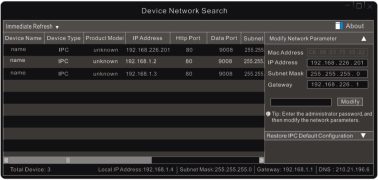
@ Modify the IP address. The default IP address of this camera is 192.168.226.201. Click the information of the camera listed in the above table to show the network information on the right hand. Modify the IP address and gateway of the camera and make sure its network address is in the same local network segment as the computer’s. Please modify the IP address of your device according to the practical situation.
2
Network Camera User Manual
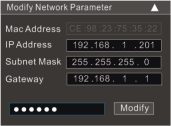
For example, the IP address of your computer is 192.168.1.4. So the IP address of the camera shall be changed to 192.168.1.X. After modification, please enter the password of the administrator and click the “Modify” button to modify the setting.
or
The default password of the administrator is “123456”.
@ Double click the IP address and then the system will pop up the IE browser to connect IP-CAM. Follow directions to download, install and run the Active X control.
[3 Remember me
Login
Enter the username and password in the login window to log in.
or
The default username is “admin”; the default password is “123456”.
3
Network Camera User Manual
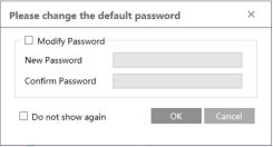
The system will pop up the above-mentioned textbox to ask you to change the default password. It is strongly recommended to change the default password for account security. If “Do not show again” is checked, the textbox will not appear next time.
The default network settings are as shown below:
IP address: 192.168.226.201
Subnet Mask: 255.255.255.0
Gateway: 192.168.226.1
HTTP: 80
Data port: 9008
Use the above default settings when logging in the camera for the first time. Directly connect the camera to the computer through network cable.

® Manually set the IP address of the PC and the network segment should be as the same as the default settings of the IP camera. Open the network and share center. Click “Local Area Connection” to pop up the following window.
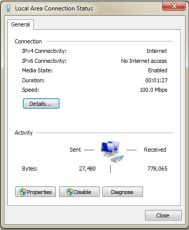
Select “Properties” and then select internet protocol according to the actual situation (for example: IPv4). Next, click the “Properties” button to set the network of the PC.
TVT Network Camera User Manual
Read More : TIGERSECU NVR XVR Firmware Upgrading Instruction
4
Network Camera User Manual
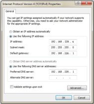
@ Open the IE browser and enter the default address of IP-CAM and confirm.
@ Follow directions to download and install the Active X control.
@ Enter the default username and password in the login window and then enter to view.
|
Name: |
admin |
|
Password: |
•••••• |
|
Stream Type: |
2592×1520 25fps |
|
Language: |
English |
> Access through the router or virtual server

® Make sure the camera is connected to the local network and then log in the camera via LAN and go to Config^Network^Port menu to set the port number.
Port Setup
@ Go to Config ^Network^TCP/IP menu to modify the IP address.
5
Network Camera User Manual
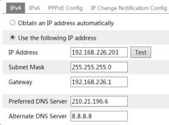
IP Setup
@ Go to the router’s management interface through IE browser to forward the IP address and port of the camera in the “Virtual Server”.
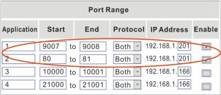
Router Setup
@ Open the IE browser and enter its WAN IP and http port to access. (for example, if the http port is changed to 81, please enter “192.198.1.201:81” in the address bar of web browser to access).
> Access through PPPoE dial-up
Network connection

Access the camera through PPPoE auto dial-up. The setup steps are as follow:
6
Network Camera User Manual
® Go to Config^Network^Port menu to set the port number.
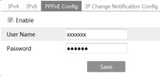
@ Go to Config ^Network^TCP/IP^PPPoE Config menu. Enable PPPoE and then enter the user name and password from your internet service provider.
@ Go to Config ^Network^DDNS menu. Before configuring the DDNS, please apply for a domain name first. Please refer to DDNS configuration for detail information.
@ Open the IE browser and enter the domain name and http port to access.
Network connection

The setup steps are as follow:
® Go to Config ^Network ^ Port menu to set the port number.
@ Go to Config ^Network^TCP/IP menu to set the IP address. Check “Use the following IP address” and then enter the static IP address and other parameters.
@ Open the IE browser and enter its WAN IP and http port to access.
7
3 Live View
After logging in, the following window will be shown.
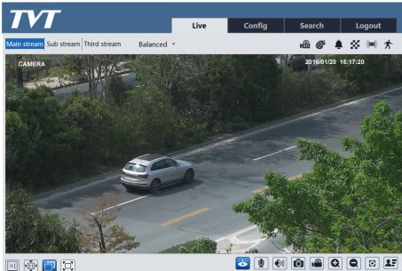
The following table is the instructions of the icons on the live view interface.
8
Network Camera User Manual
Those smart alarm indicators will flash only when the camera supports those functions and the corresponding events are enabled.
In full screen mode, double click on the mouse to exit or press the ESC key on the keyboard. Click AZ control button to show AZ control panel. The descriptions of the control panel are as follows:
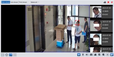
Face Capture View
@ Go to Config^Event^Face Detection interface. Check “Enable”.
@ Return to the live view interface. Click to go to the following interface. When there are faces detected, the face pictures will be listed on the right.
9
4 Network Camera Configuration
In the Webcam client, choose “Config” to go to the configuration interface.
Note: Wherever applicable, click the “Save” button to save the settings.
|
HTTP Port |
80 1 |
|
HTTPS Port |
1 |
|
Data Port |
9008 | |
|
RTSP Port |
1 |
|
Icon |
Description |
Icon |
Description |
||
|
|
H |
Original size |
H |
Sensor alarm indicator |
|
|
|
I® |
Fit correct scale |
|
Motion alarm indicator |
|
|
|
a |
|
Auto (fill the window) |
|
Color abnormal indicator |
|
|
Hl |
|
Full screen |
A |
Abnormal clarity indicator |
|
|
<> |
|
Start/stop live view |
fl? |
Scene change indicator |
|
LU |
Start/stop two-way audio (only available for the model with audio input connector) |
|
Line crossing indicator |
||
|
g |
Enable/disable audio |
O) |
Intrusion indicator |
||
|
|
Snapshot |
|
Region entrance indicator (only some models support) |
||
|
Icon |
Description |
Icon |
Description |
|
|
|
|
Start/stop local recording |
*1 |
Region exiting indicator(only some models support) |
|
|
oi |
Zoom in |
|
Face detection indicator |
|
|
®l |
Zoom out |
hl |
Target counting indicator |
|
L+J |
AZ control (only available for the model with motorized zoom lens ) |
XF |
Face capture |
|
|
|
SD card recording indicator |
|
|
|
|
Icon |
Description |
Icon |
Description |
||
|
|
w |
|
Zoom – |
4 |
Zoom + |
|
|
x |
|
Focus – |
|
Focus + |
|
|
© |
|
One key focus (used when image is out of focus after manual adjustment |
||
In the “Basic Information” interface, the system information of the device is listed.
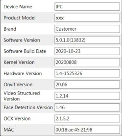
Some versions may support device ID and QR code. If P2P is enabled (see Network Configuration–P2P), the network camera can be quickly added to mobile surveillance client, by scanning the QR code or entering device ID.
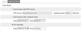
Go to Config^System^Date and Time. Please refer to the following interface.
10
Network Camera User Manual
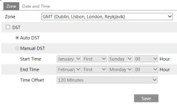
Select the time zone and DST as required.
Click the “Date and Time” tab to set the time mode.
Go to Config^System^Local Config to set up the storage path of captured pictures and recorded videos on the local PC. There is also an option to enable or disable the bitrate display in the recorded files.

Additionally, “Local smart snapshot storage” can be enabled or disabled here. If enabled, the captured pictures triggered by smart events (like line crossing detection, region intrusion, etc.) will be saved to the local PC.
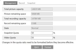
Click the “Format” button to format the SD card. All data will be cleared by clicking this button.
Click the “Eject” button to stop writing data to SD card. Then the SD card can be ejected safely.
Snapshot Quota: Set the capacity proportion of captured pictures on the SD card.
Video Quota: Set the capacity proportion of record files on the SD card.
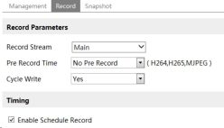
Pre Record Time: Set the time to record before the actual recording begins.
12
Network Camera User Manual
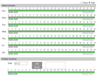
Set the alarm time from Monday to Sunday for a single week. Each day is divided in one hour increments. Green means scheduled. Blank means unscheduled.
“Add”: Add the schedule for a special day. Drag the mouse to set the time on the timeline.
“Erase”: Delete the schedule. Drag the mouse to erase the time on the timeline.
Manual Input: Click it for a specific day to enter specific start and end times. This adds more granularities (minutes).
Set the alarm time for alarm a special day, such as a holiday.
Note: Holiday schedule takes priority over weekly schedule.
• Snapshot Settings
Go to Config^System^Storage^Snapshot to go to the interface as shown below.
13
Network Camera User Manual
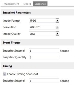
Set the format, resolution and quality of the image saved on the SD card and the snapshot interval and quantity and the timing snapshot here.
Snapshot Quantity: The number you set here is the maximum quantity of snapshots. The actual quantity of snapshots may be less than this number. Supposing the occurrence time of an alarm event is less than the time of capturing pictures, the actual quantity of snapshots is less than the set quantity of snapshots.
Timing Snapshot: Enable timing snapshot first and then set the snapshot interval and schedule. The setup steps of schedule are the same as the schedule recording (See Schedule Recording).
Go to Image^Display interface as shown below. The image’s brightness, contrast, hue and saturation and so on for common, day and night mode can be set up separately. The image effect can be quickly seen by switching the configuration file.
14
Network Camera User Manual
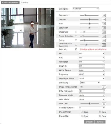
Brightness: Set the brightness level of the camera’s image.
Contrast: Set the color difference between the brightest and darkest parts.
Hue: Set the total color degree of the image.
Saturation: Set the degree of color purity. The purer the color, the brighter the image is.
Sharpness: Set the resolution level of the image plane and the sharpness level of the image edge.
Noise Reduction: Decrease the noise and make the image more thorough. Increasing the value will make the noise reduction effect better but it will reduce the image resolution.
Defog: Activating this function and setting an appropriate value as needed in foggy, dusty, smoggy or rainy environment to get clear images.
Lens Distortion Correction: When the image appears distortion to some extent, please enable this function and adjust the level according to the actual scene to correct the distortion. (Only some version may support this function. If your camera doesn’t support it, please skip this instruction.)
Auto Iris: If your camera is auto Iris, please enable it.
Backlight Compensation (BLC):
Network Camera User Manual
Recording will be stopped for a few seconds while the mode is changing from non-WDR to WDR mode.
HFR: High Frame Rate. If “ON” is selected, the system will restart and then the maximum value of the frame rate of the main stream can be set to 60 fps /50fps.
Antiflicker:
Smart IR: Choose “ON” or “OFF”. This function can effectively avoid image overexposure and underexposure by controlling the brightness of the IR lights according to the actual conditions to make the image more realistic. Please enable it as needed.
White Balance: Adjust the color temperature according to the environment automatically.
Frequency: 50Hz and 60Hz can be optional.
Day/Night Mode: Choose “Auto”, “Day”, “Night” or “Timing”.
Infra-red Mode: Choose “Auto”, “ON” or “OFF”.
Exposure Mode: Choose “Auto” or “Manual”. If manual is chosen, the digital shutter speed can be adjusted.
Gain Mode: Choose “Auto” or “Manual”. If “Auto” is selected, the gain value will be automatically adjusted according to the actual situation. If “Manual” is selected, the gain value shall be set manually. The higher the value is, the brighter the image is.
Corridor Pattern: Corridor viewing modes can be used for situations such as long hallways. 0, 90, 180 and 270 are available. The default value is 0. The video resolution should be 1080P or below if this function is used.
Image Mirror: Turn the current video image horizontally.
Image Flip: Turn the current video image vertically.
Schedule Settings of Image Parameters:
Click the “Schedule” tab as shown below.

Set full time schedule for common, day, night mode and specified time schedule for day and
16
Network Camera User Manual
night. Choose “Schedule” in the drop-down box of schedule as shown below.
Drag “‘_” icons to set the time of day and night. Blue means day time and blank means night time. If the current mode of camera parameters is set to schedule, the image configuration mode will automatically switch between day and night according to the schedule.
|
Schedule |
Timing |
|
|||||
|
Time Range |
■■ 0:00 |
4:00 |
8:00 |
12:00 |
16:00 |
20:00 |
■■■ 24:00 |
|
|
■ Day |
□ Night |
|
|
|
|
|
Go to Image^Video / Audio interface as shown below. In this interface, set the resolution, frame rate, bitrate type, video quality and so on subject to the actual network condition.
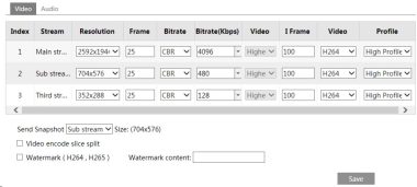
Click the “Audio” tab to go to the interface as shown below.
Video
Audio
0 Enable
Audio Encoding
Audio Type
UN In Volume
Audio Out Volume

Three video streams can be adjustable.
Resolution: The size of image.
Frame rate: The higher the frame rate, the video is smoother.
17
Network Camera User Manual
Bitrate type: CBR and VBR are optional. Bitrate is related to image quality. CBR means that no matter how much change is seen in the video scene, the compression bitrate will be kept constant. VBR means that the compression bitrate will be adjusted according to scene changes. For example, for scenes that do not have much movement, the bitrate will be kept at a lower value. This can help optimize the network bandwidth usage.
Bitrate: it can be adjusted when the mode is set to CBR. The higher the bitrate, the better the image quality will be.
Video Quality: It can be adjusted when the mode is set to VBR. The higher the image quality, the more bitrate will be required.
I Frame interval: It determines how many frames are allowed between a “group of pictures”. When a new scene begins in a video, until that scene ends, the entire group of frames (or pictures) can be considered as a group of pictures. If there is not much movement in the scene, setting the value higher than the frame rate is fine, potentially resulting in less bandwidth usage. However, if the value is set too high, and there is a high frequency of movement in the video, there is a risk of frame skipping.
Video Compression: MJPEG, H264+, H264,H264S, H265, H265+, H265S can be optional. MJPEG is not available for main stream. Compared to H.265, H.265+ saves more storage space with the same maximum bitrate in most scenes. Compared to H.264, H.265 reduces the transmission bitrate under the same resolution, frame rate and image quality. Compared to H.265+/H.265, smart H.265 can spontaneously adjust the bitrate distribution according to the requirements of the actual scene. For example, when there is no human or vehicle detected, the bitrate will be automatically reduced with no effect on image quality by using H.265S. If H.265/H.265+/H.265S is chosen, make sure the client system is able to decode H.265/H.265+/H.265S.
Profile: For H.264. Baseline, main and high profiles are selectable.
Send Snapshot: How many snapshots to generate for an event.
Video encode slice split: If this function is enabled, smooth image can be gotten even though using the low-performance PC.
Watermark: When playing back the local recorded video in the search interface, the watermark can be displayed. To enable it, check the watermark box and enter the watermark text.
Audio Encoding: G711A and G711U are selectable.
Audio Type: LIN. MIC can be optional for the model with built-in MIC.
LIN IN/MIC IN Volume: LIN IN Volume can be set here. If MIC is selected, MIC IN volume can be set.
Audio Out Volume: This function is available for the model with audio out interface.
Go to Image^OSD interface as shown below.
18
Network Camera User Manual
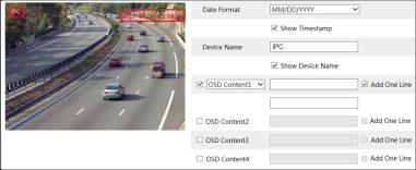
Set time stamp, device name, OSD content and picture overlap here. After enabling the corresponding display and entering the content, drag them to change their position. Then click the “Save” button to save the settings.
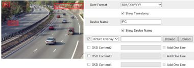
Picture Overlay Settings:
Check “OSD Content1”, choose “Picture Overlay” and click “Browse” to select the overlap picture. Then click “Upload” to upload the overlap picture. The pixel of the image shall not exceed 200*200, or it cannot be uploaded.
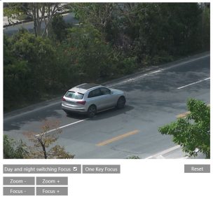
This function is only available for the model with motorized zoom lens. Within this section, zoom and focus can be controlled. If the image is out of focus after a manual adjustment, one key focus can be used to set the focus automatically. Go to Config^ Imaged Zoom/Focus interface to set.
21
Network Camera User Manual
This function is only available for the model with RS485 interface. It can be used with a compatible external PTZ enclosure. Go to PTZ ^Protocol interface as shown below.
Protocol | PELCOD v
Address 1 |
Baud-Rate 12400 v
Save
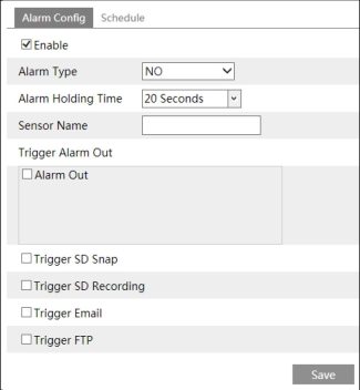
Go to Alarm^Motion Detection to set motion detection alarm.
22
Network Camera User Manual
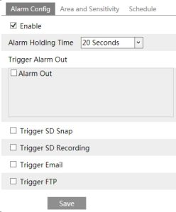
Alarm Out: If selected, this would trigger an external relay output that is connected to the camera on detecting a motion based alarm.
Trigger Snap: If selected, the system will capture images on motion detection and save the images on an SD card.
Trigger SD Recording: If selected, video will be recorded on an SD card on motion detection.
Trigger Email: If “Trigger Email” and “Attach Picture” are checked (email address must be set first in the Email configuration interface), the captured pictures and triggered event will be sent into those addresses.
Trigger FTP: If “Trigger FTP” and “Attach Picture” are checked, the captured pictures will be sent into FTP server address. Please refer to FTP configuration chapter for more details.
23
Network Camera User Manual
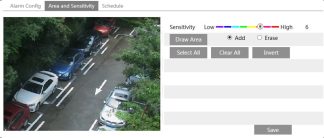
Move the “Sensitivity” scroll bar to set the sensitivity. Higher sensitivity value means that motion will be triggered more easily.
Select “Add” and click “Draw”. Drag the mouse to draw the motion detection area; Select “Erase” and drag the mouse to clear motion detection area.
After that, click the “Save” to save the settings.
This function is only available for the models with Alarm Out interface.
This function is only available for some models. Go to Config ^Alarm^ Alarm Out.
26
Network Camera User Manual
Alarm Out Mode: Alarm linkage, manual operation, day/night switch linkage and timing are optional.
Alarm Linkage: Having selected this mode, select alarm out name, alarm holding time at the “Alarm Holding Time” pull down list box and alarm type.
Manual Operation: Having selected this mode, select the alarm type and click “Open” to trigger the alarm out immediately; click “Close” to stop alarm.
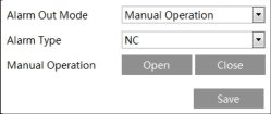
Day/Night Switch Linkage: Having selected this mode, select the alarm type and then choose to open or close alarm out when the camera switches to day mode or night mode.
Alarm Out Mode
Alarm Type
Day
Night

Timing: Select the alarm type. Then click “Add” and drag the mouse on the timeline to set the schedule of alarm out; click “Erase” and drag the mouse on the timeline to erase the set time schedule. After this schedule is saved, the alarm out will be triggered in the specified time.
27
Network Camera User Manual

|
Alarm Out Mode |
| Alarm Linkage |
Id |
|
Alarm Out Name |
alarmOutl |
|
|
Alarm Holding Time |
|20 Seconds |
u |
|
Alarm Type |
NC |
H |
For more accuracy, here are some recommendations for installation.
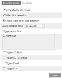
Scene Change Detection: Alarms will be triggered if the scene of the monitor video has changed.
Video Blur Detection: Alarms will be triggered if the video becomes blurry.
Enable Video Color Cast Detection: Alarms will be triggered if the video becomes obscured.

Drag the slider to set the sensitivity value or directly enter the sensitivity value in the textbox. Click “Save” button to save the settings.
The sensitivity value of Scene Change Detection: The higher the value is, the more sensitive the system responds to the amplitude of the scene change.
The sensitivity value of Video Blur Detection: The higher the value is, the more sensitive
29
Network Camera User Manual
the system responds to the blurriness of the image.
The sensitivity value of Video Color Cast Detection: The higher the value is, the more sensitive the system responds to the obscuring of the image.
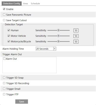
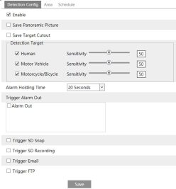
Save Panoramic Picture: If it is enabled, the detected panoramic pictures will be captured and saved to the SD card when the targets cross the alarm line.
Save Target Cutout: If it is enabled, the detected target cutout pictures will be captured and saved to the SD card when the targets cross the alarm line.
Note: To save snapshots to the local PC, please enable “Local Smart Snapshot Storage” in the local config interface first. To save snapshots to the SD card, please install an SD card first.
30
Network Camera User Manual
Human: Select it and then alarms will be triggered if someone crosses the pre-defined alarm lines.
Motor Vehicle: Select it and then alarms will be triggered if a vehicle with four or more wheels (eg. a car, bus or truck) crosses the pre-defined alarm lines.
Motorcycle/Bicycle: Select it and then alarms will be triggered if a vehicle with two wheels (eg. a motorcycle or bicycle) crosses the pre-defined alarm lines.
All of the three types of objects can be selected simultaneously. Please select the detection objects as needed. If no object/target is selected, alarms will not be triggered even if line crossing detection is enabled.
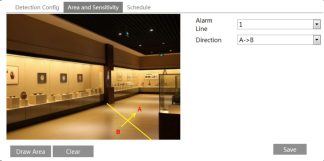
Set the alarm line number and direction. Up to 4 lines can be added. Multiple lines cannot be added simultaneously.
Direction: A<->B, A->B and A<-B optional. This indicates the direction of someone or a vehicle crosses over the alarm line.
A<->B: Alarms will be triggered when someone or a vehicle crosses over the alarm line from B to A or from A to B.
A->B: Alarms will be triggered when someone or a vehicle crosses over the alarm line from A to B.
A<-B: Alarms will be triggered when someone or a vehicle crosses over the alarm line from B to A.
Click the “Draw Area” button and then drag the mouse to draw a line in the image. Click the “Stop Draw” button to stop drawing. Click the “Clear” button to delete the lines. Click the “Save” button to save the settings.
31
Network Camera User Manual
Intrusion: Alarms will be triggered if the target intrudes into the pre-defined areas. This function can be applicable to important supervision places, danger areas and prohibited areas, like military administrative zones, high danger areas, no man’s areas, etc.
Go to ConfigAEventAIntrusion interface as shown below.
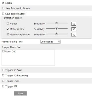
Save Panoramic Picture: If it is enabled, the detected panoramic pictures will be captured and saved to the SD card when the targets intrude into the pre-defined areas.
32
Network Camera User Manual
Save Target Cutout: If it is enabled, the detected target cutout pictures will be captured and saved to the SD card when the targets intrude into the pre-defined areas.
Note: To save snapshots to the local PC, please enable “Local Smart Snapshot Storage” in the local config interface first. To save snapshots to the SD card, please install an SD card first.
Detection Target:
Human: Select it and then alarms will be triggered if someone intrudes into the pre-defined area.
Motor Vehicle: Select it and then alarms will be triggered if a vehicle with four or more wheels (eg. a car, bus or truck) intrudes into the pre-defined area.
Motorcycle/Bicycle: Select it and then alarms will be triggered if a vehicle with two wheels (eg. a motorcycle or bicycle) intrudes into the pre-defined area.
All of the three types of objects can be selected simultaneously. Please select the detection objects as needed. If no object/target is selected, alarms will not be triggered even if intrusion detection is enabled.
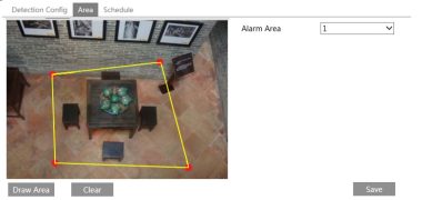
Set the alarm area number on the right side. Up to 4 alarm areas can be added.
Click the “Draw Area” button and then click around the area where you want to set as the alarm area in the image on the left side (the alarm area should be a closed area). Click the “Stop Draw” button to stop drawing. Click the “Clear” button to delete the alarm area. Click the “Save” button to save the settings.
33
Network Camera User Manual
Save Panoramic Picture: If it is enabled, the detected panoramic pictures will be captured and saved to the SD card when the targets enter the pre-defined areas.
Save Target Cutout: If it is enabled, the detected target cutout pictures will be captured and saved to the SD card when the targets enter the pre-defined areas.
Note: To save snapshots to the local PC, please enable “Local Smart Snapshot Storage” in the local config interface first. To save snapshots to the SD card, please install an SD card first.
Detection Target:
Human: Select it and then alarms will be triggered if someone enters the pre-defined area.
Motor Vehicle: Select it and then alarms will be triggered if a vehicle with four or more wheels (eg. a car, bus or truck) enters the pre-defined area.
Motorcycle/Bicycle: Select it and then alarms will be triggered if a vehicle with two wheels
34
Network Camera User Manual
(eg. a motorcycle or bicycle) enters the pre-defined area.
All of the three types of objects can be selected simultaneously. Please select the detection objects as needed. If no object/target is selected, alarms will not be triggered even if region entrance detection is enabled.
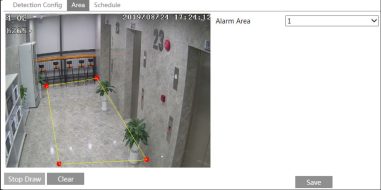
Set the alarm area number on the right side. Up to 4 alarm areas can be added.
Click the “Draw Area” button and then click around the area where you want to set as the alarm area in the image on the left side (the alarm area should be a closed area). Click the “Stop Draw” button to stop drawing. Click the “Clear” button to delete the alarm area. Click the “Save” button to save the settings.
* The configuration requirements of camera and surrounding area are the same as intrusion detection.
Save Panoramic Picture: If it is enabled, the detected panoramic pictures will be captured and saved to the SD card when the targets exit from the pre-defined areas.
Save Target Cutout: If it is enabled, the detected target cutout pictures will be captured and saved to the SD card when the targets exit from the pre-defined areas.
Note: To save snapshots to the local PC, please enable “Local Smart Snapshot Storage” in the local config interface first. To save snapshots to the SD card, please install an SD card first.
Detection Target:
Human: Select it and then alarms will be triggered if someone exits from the pre-defined area.
Motor Vehicle: Select it and then alarms will be triggered if a vehicle with four or more wheels (eg. a car, bus or truck) exits from the pre-defined area.
Motorcycle/Bicycle: Select it and then alarms will be triggered if a vehicle with two wheels (eg. a motorcycle or bicycle) exits from the pre-defined area.
All of the three types of objects can be selected simultaneously. Please select the detection objects as needed. If no object/target is selected, alarms will not be triggered even if region exiting detection is enabled.
36
Network Camera User Manual
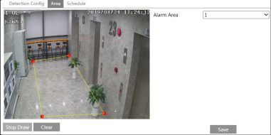
Set the alarm area number on the right side. Up to 4 alarm areas can be added.
Click the “Draw Area” button and then click around the area where you want to set as the alarm area in the image on the left side (the alarm area should be a closed area). Click the “Stop Draw” button to stop drawing. Click the “Clear” button to delete the alarm area. Click the “Save” button to save the settings.
* The configuration requirements of camera and surrounding area are the same as intrusion detection
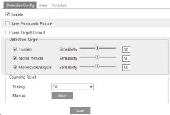
Save Panoramic Picture: If it is enabled, the detected panoramic pictures will be captured and saved to the SD card when the targets cross the pre-defined alarm line.
Save Target Cutout: If it is enabled, the detected target cutout pictures will be captured and
37
Network Camera User Manual
saved to the SD card when the targets cross the pre-defined alarm line.
Note: To save snapshots to the local PC, please enable “Local Smart Snapshot Storage” in the local config interface first. To save snapshots to the SD card, please install an SD card first.
Detection Target: Select the target to calculate. Human, motor vehicle and motorcycle/bicycle can be selected.
Counting Reset: The current number of the target counting can be reset. You can choose to reset the counting daily, weekly or monthly. Click “Reset” to manually reset the current number of crossing line people/car/bike counting.
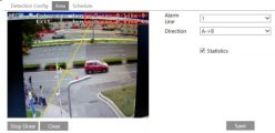
Set the alarm line number and direction. Only one alarm line can be added.
Direction: A->B and A<-B can be optional. The direction of the arrow is entrance.
Click the “Draw Area” button and then drag the mouse to draw a line in the image. Click the “Stop Draw” button to stop drawing. Click the “Clear” button to delete the lines.
Statistics: If enabled, you can see the statistical information in the live view interface. If disabled, the statistical information will not be displayed in the live view interface.
Check “Statistics” and then move the red box to change the position of the statistical information displayed on the screen. Click the “Save” button to save the settings.
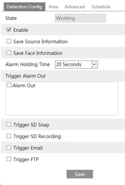
Save Source Information: if checked, the whole picture will be saved to the SD card when detecting a face.
Save Face Information: if checked, the captured face picture will be saved to the SD card when detecting a face.
Note: To save images to the local PC, please enable the local smart snapshot storage first (Config^System^Local Config). To save images to the SD card, please install an SD card first.
39
Network Camera User Manual
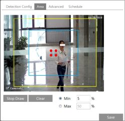
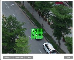
Click “Draw Area” and drag the border lines of the rectangle to modify its size. Move the rectangle to change its position. Click “Stop Draw” to stop drawing the area. Click “Clear” to clear the area. Then set the detectable face size by defining the maximum value and the minimum value (The default size range of a single face image occupies from 3% to 50% of the entire image).
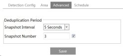
Snapshot Interval: If 5 seconds is selected, the camera will capture the same target once every 5 seconds during its continuous tracking period.
Snapshot Number: If the snapshot number is enabled and set (eg. 3), the camera will capture the same target once every 5 seconds and it will capture this target 3 times at most during its continuous tracking period. If the snapshot number is disabled, the camera will capture the same target once every 5 seconds until the target disappears in the detected area.
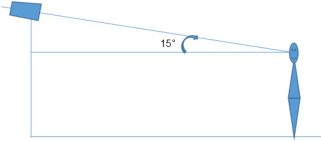
^ Configuration requirements of camera and surrounding area
40
Network Camera User Manual
Go to Conlig^Network^TCP/IP interface as shown below. There are two ways for network connection.
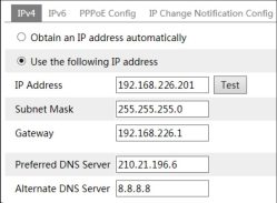
Use IP address (take IPv4 for example)-There are two options for IP setup: obtain an IP address automatically by DHCP and use the following IP address. Please choose one of the options as needed.
Test: Test the effectiveness of the IP address by clicking this button.
Use PPPoE-Click the “PPPoE Config” tab to go to the interface as shown below. Enable
41
Network Camera User Manual
PPPoE and then enter the user name and password from your ISP.
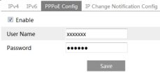
Either method of network connection can be used. If PPPoE is used to connect internet, the camera will get a dynamic WAN IP address. This IP address will change frequently. To be notified, the IP change notification function can be used.
Click “IP Change Notification Config” to go to the interface as shown below.

Trigger Email: when the IP address of the device is changed, the new IP address will be sent to the email address that has been set up.
Trigger FTP: when the IP address of the device is changed, the new IP address will be sent to FTP server that has been set up.
Go to Config^Network^Port interface as shown below. HTTP port, Data port and RTSP port can be set.
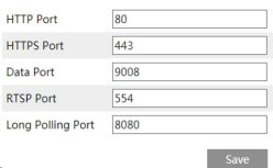
HTTP Port: The default HTTP port is 80. It can be changed to any port which is not occupied.
HTTPS Port: The default HTTPs port is 443. It can be changed to any port which is not
42
Network Camera User Manual
occupied. (Some models may not support )
Data Port: The default data port is 9008. Please change it as necessary.
RTSP Port: The default port is 554. Please change it as necessary.
Long Polling Port: The port is used for a persistent connection of the third-party platform to push smart data, like face pictures.
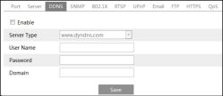
Enter www.dvrdydns.com in the IE address bar to visit its website. Then Click the “Registration” button.
43
Network Camera User Manual
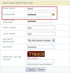
Create domain name.
fbu must create a domain name to cont/nue.
Domain name must start with (a-z, 0-9). Cannot end or start, but may contain a hyphen and is not case-sensitive.
I J dwdyihs.com v~| [ Request Domaln ]
After the domain name is successfully applied for, the domain name will be listed as below.
|
Search by Domain. |
| Search | |
Click a name to edit your domain settings. |
|
NAME |
STATUS |
DOMAIN |
|
654321 ABC |
© |
654321abc.dvrdydns.com 1 |
|
Last Update: Notyetupda |
W IP Address: 210.21.22y.ua |
|
|
Crea^iwMfion^domain named |
|
|
Note: Please use the different version in accordance with the security level you required. The higher the version is, the higher the level of the security is.
If it is enabled, the camera’s data can be protected. When the camera is connected to the network protected by the IEE802.1x, user authentication is needed.
45
Network Camera User Manual
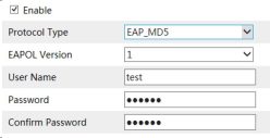
To use this function, the camera shall be connected to a switch supporting 802.1x protocol. The switch can be reckoned as an authentication system to identify the device in a local network. If the camera connected to the network interface of the switch has passed the authentication of the switch, it can be accessed via the local network.
Protocol type and EAPOL version: Please use the default settings.
User name and password: The user name and password must be the same with the user name and password applied for and registered in the authentication server.
Go to Config^Network^RTSP.
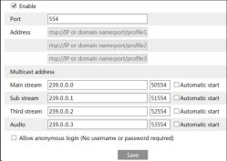
Select “Enable” to enable the RTSP function.
Port: Access port of the streaming media. The default number is 554.
RTSP Address: The RTSP address (unicast) format that can be used to play the stream in a media player.
Main stream: The address format is
“rtsp://IP address: rtsp port/profile1?transportmode=mcast”.
Sub stream: The address format is
“rtsp://IP address: rtsp port/profile2?transportmode=mcast”.
Third stream: The address format is
46
Network Camera User Manual
“rtsp://IP address: rtsp port/profile3?transportmode=mcast”.
Audio: Having entered the main/sub stream in a VLC player, the video and audio will play automatically.
If “Allow anonymous login…” is checked, there is no need to enter the username and password to view the video.
If “auto start” is enabled, the multicast received data should be added into a VLC player to play the video.
Note:1. This camera support local play through a VLC player. Enter the RTSP address (unicast or multicast, eg. rtsp://192.168.226.201:554/profile1?transportmode=mcast) in a VLC player to realize the simultaneous play with the web client.
If this function is enabled, the camera can be quickly accessed through the LAN.
Go to Config^Network^UPnP. Enable UPNP and then enter UPnP name.

If you need to trigger Email when an alarm happens or IP address is changed, please set the Email here first.
Go to Conlig^Network ^Email.
47
Network Camera User Manual
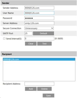
Sender Address: sender’s e-mail address.
User name and password: sender’s user name and password.
Server Address: The SMTP IP address or host name.
Select the secure connection type at the “Secure Connection” pull-down list according to what’s required.
SMTP Port: The SMTP port.
Send Interval(S): The time interval of sending email. For example, if it is set to 60 seconds and multiple motion detection alarms are triggered within 60 seconds, they will be considered as only one alarm event and only one email will be sent. If one motion alarm event is triggered and then another motion detection alarm event is triggered after 60 seconds, two emails will be sent. When different alarms are triggered at the same time, multiple emails will be sent separately.
Click the “Test” button to test the connection of the account.
Recipient Address: receiver’s e-mail address.
After an FTP server is set up, captured pictures from events will be uploaded to the FTP server.
Go to Config ^Network ^FTP.
48
Network Camera User Manual
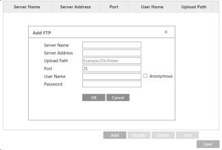
Server Name: The name of the FTP server.
Server Address: The IP address or domain name of the FTP.
Upload Path: The directory where files will be uploaded to.
Port: The port of the FTP server.
User Name and Password: The username and password that are used to login to the FTP server.
HTTPs provides authentication of the web site and protects user privacy. Go to Config ^Network^HTTPS as shown below.
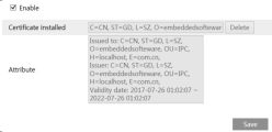
There is a certificate installed by default as shown above. Enable this function and save it. Then the camera can be accessed by entering https://IP: https port via the web browser (eg. https://192.168.226.201:443).
A private certificate can be created if users don’t want to use the default one. Click “Delete” to cancel the default certificate. Then the following interface will be displayed.
Network Camera User Manual

Enable
Create a private certificate I Create
![]()
Click the “Create” button to create a private certificate. Enter the country (only two letters available), domain (camera’s IP address/domain), validity date, password, province/state, region and so on. Then click “OK” to save the settings.
* Click “Create a certificate request” to enter the following interface.
□ Enable
Installation type O Have signed certificate, install directly
O Create a private certificate
® Create a certificate request
Create a certificate request Create Download Delete
Click “Create” to create the certificate request. Then download the certificate request and submit it to the trusted certificate authority for signature. After receiving the signed certificate, import the certificate to the device.
|
Installation type |
0 Have signed certificate, install directly @ Create a private certificate O Create a certificate request |
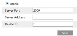
If this function is enabled, the network camera can be quickly accessed by adding the device ID in mobile surveillance client or CMS/NVMS client via WAN. Enable this function by going to Conlig^Network^P2P interface.

50
Network Camera User Manual
QoS (Quality of Service) function is used to provide different quality of services for different network applications. With the deficient bandwidth, the router or switch will sort the data streams and transfer them according to their priority to solve the network delay and network congestion by using this function.
Go to Config^Network^QoS.
Video/Audio DSCP: The range is from 0 to 63.
Alarm DSCP: The range is from 0 to 63.
Manager DSCP: The range is from 0 to 63.
Generally speaking, the larger the number is, the higher the priority is.
|
Vldeo/Audlo DSCP |
1 |
|
Alarm DSCP |
I35 1 |
|
Manager DSCP |
1 |
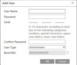
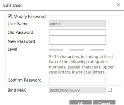
It is recommended to set a high level password that shall be composed of numbers, special characters, upper or lower case letters for your account security.
If this option is enabled, only the PC with the specified MAC address can access the camera for that user.
Go to Config^Security^Online User to view the user who is viewing the live video.
![]()
An administrator user can kick out all the other users (including other administrators).
Go to Config^Security^Block and Allow Lists as shown below.
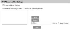
The setup steps are as follows:
Check the “Enable address filtering” check box.
Select “Block/Allow the following address”, IPv4/IPv6/MAC and then enter IP address or MAC address in the address box and click the “Add” button.
Go to Config^Security^Security Management as shown below.

In order to prevent against malicious password unlocking, “locking once illegal login” function can be enabled here. If this function is enabled, login failure after trying six times will make the login interface locked. The camera can be logged in again after a half hour or after the camera reboots.
Go to Config^Maintenance^Reboot.
Click the “Reboot” button to reboot the device.
If necessary, the camera can be set up to reboot on a time interval. Enable “Time Settings”, set the date and time and then click the “Save” button to save the settings.
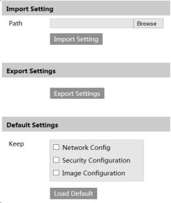
Go to Config^Maintenance^Upgrade. In this interface, the camera firmware can be updated.
54
Network Camera User Manual
![]()
|
Main Type: | All log |
v Sub Type: | All log |
|
|
|
|
Start Time: |2015-07-14 00:00:00 |
Ü End Time: |2015-07-14 23:59:59 S3 H |
Search | Export | |
||
|
Index |
Time |
Main Type Sub Type |
User Name |
Login IP |
|
1 |
2015-07-14 11:15:18 |
Operation Log in |
admin |
192.168.12.53 |
|
2 |
2015-07-14 11:12:02 |
Exception Disconnected |
|
192.168.12.53 |
|
3 |
2015-07-14 19:12:17 |
Exception Disconnected |
|
192.168.12.52 |
|
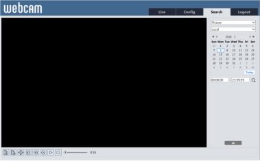
Icon |
Description |
Icon |
Description |
|
Id |
Close: Select an image and click this button to close the image. |
IBI |
Close all: Click this button to close all images. |
|
d |
Save: Click this button to select the path for saving the image on the PC. |
tâ |
Save all: Click this button to select the path for saving all pictures on the PC. |
|
|
Fit size: Click to fit the image on the screen. |
H |
Actual size: Click this button to display the actual size of the image. |
|
@ |
Zoom in: Click this button to digitally zoom in. |
Q |
Zoom out: Click this button to digitally zoom out. |
|
|
Slide show play: Click this button to start the slide show mode. |
□ |
Stop: Click this button to stop the slide show. |
|
®[55S| |
Play speed: Play speed of the slide show. |
||
|
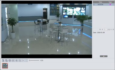
Icon |
Description |
Icon |
Description |
|
|
Play button. After pausing the video, click this button to continue playing. |
IL |
Pause button |
|
|
Stop button |
|
Speed down |
|
|
Speed up |
4 |
Watermark display |
|
Q > i =□ |
Enable / disable audio; drag the slider to adjust the volume after enabling audio. |
||
Network Camera User Manual

Click “Set up” to set the storage directory of the video files.
Click “Open” to play the video.
Click “Clear List” to clear the downloading list.
Click “Close” to close the downloading window.
61
A: Reset the device to the default factory settings.
Default IP: 192.168.226.201; User name: admin; Password: 123456
Fail to connect devices through IE browser.
A: Network is not well connected. Check the connection and make sure it is connected well.
B: IP address is not available. Reset the IP address.
C: Web port number has been changed: contact administrator to get the correct port number.
D: Exclude the above reasons. Restore to default setting by IP-Tool.
IP tool cannot search devices.
It may be caused by the anti-virus software in your computer. Please exit it and try to search device again.
IE cannot download ActiveX control.
A. IE browser may be set up to block ActiveX. Follow the steps below.
® Open IE browser and then click Tools Internet Options.
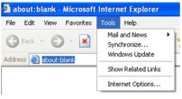
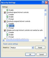
@ Select Security Custom Level….
® Enable all the options under “ActiveX controls and plug-ins”.
@ Click OK to finish setup.
B. Other plug-ins or anti-virus blocks ActiveX. Please uninstall or close them.
Network Camera User Manual
Internet Options
| Privacy || Content ||
Select a Web content zone to specify its security settings.
Internet Local intranet Trusted sites
Restricted
Internet
This zone contains all Web sites you
Ml haven’t placed i
Security level for this zone
I in other zones
Custom
Custom settings.
■ T o change the settings, click Custom Level.
• To use the recommended settings, click Default Level.
[ Custom Level… | [ Default Level [
[ OK. | [ Cancel j [ Apply
A: Audio input device is not connected. Please connect and try again.
B: Audio function is not enabled at the corresponding channel. Please enable this function.
63











Add Comment