Production Introduction
The NVR series is a HD surveillance product that designed for security field. It uses an embedded operating system to ensure stable system performance. It adopts the standard H.265 video compression algorithm and a unique spatial-temporal filtering algorithm to achieve high-quality, low-bitrate synchronous audio and video and 24/7 video recording. With TCP/IP network technologies, it has powerful network data transmission and remote control capabilities.
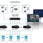
The NVR can be used locally or online applied as a part of a safety surveillance network. With professional network video surveillance software, it fully demonstrates its strong networking and telecommunication capabilities.
This NVR can be applied to security measures in various fields and departments such as banking, telecommunications, electric power system, judiciary system, transportation, smart communities, factories, warehouses and water facilities.
Unboxing and Initial Setup
When you receive this product, please confirm that it matches the model you ordered and carefully inspect the device for any obvious damage. After opening the casing, check whether the data cable, power cable, and other connections inside the device are firmly connected to the main board.
Please protect the labels attached to the bottom or back panel, which is very important to our after-sales service work. When contacting our company for after-sales service, you will need to provide the model and serial number on the order label.

![]()
or
NVR Power Supply USB Mouse
![]()
![]()
Quick Start Guide
Ethernet Cable HDMI Cable Quick Start Guide
Note: Products and accessories vary by product models, please refer to the actual product.
➊ Antenna
USB Backup
Network Port
HDMI Port
VGA Port Audio Port
USB Mouse Power Port
❷ Antenna
HDMI Port
LAN Port USB 2.0 Port Type-C
NOTE: The picture shown is for reference only. Actual appearance is subject to the model you purchased.
➊
USB Backup
4
Monitor
3
2
1
Route
❷
USB 2.0 Port
LAN Port
Battery Camera
3
1
2
4
ZOSI Wireless NVR Detail User Manual
Read More : How to set up Zosi POE NVR System
![]()
HDMI Port Type-C
Ⓒ Connect the NVR to the Router with Ethernet Cable.
Ⓒ Connect the NVR to the Monitor with HDMI Cable or VGA Cable. (VGA Cable is not included)
Ⓒ Connect the USB Mouse to the USB2.0 Port.
Ⓐ Connect the NVR to the Power Supply.
Ⓒ The monitor will display live view of the camera.
NOTE: To ensure the device works properly, it is recommended to power on the NVR first for testing before a final installation.
Via Smartphone
![]() Search “ZOSI” in App Store, or use a browser to scan the QR code below to download and install the App, and follow the on-screen instructions to complete the initial setup.
Search “ZOSI” in App Store, or use a browser to scan the QR code below to download and install the App, and follow the on-screen instructions to complete the initial setup.
![]()
![]() App video operation link
App video operation link
Via PC
Download: https://www.zositech.com/app/
Basic Operation
After connecting the power supply, the power indicator light will turn on, and the device
will start up. At this time, you will hear a “beep” from the buzzer. By default, the system is in multi-screen mode.
Mouse Use:
Left-click:
Double-click a single-channel to make it full screen, and double-click again to return to the multi-channel display.
Left-click
Right-click
After the device is powered on normally, you need to log in to the system before operating it. The system will provide corresponding functions according to the permissions of the logged-in user.
The default for the device is “admin” and the default password is blank. You can log in to the system directly the first time after powering on.
After entering the preview page, double-click the left mouse button to switch between single or multiple display. On each preview screen, the date, time, and channel name can be displayed, and each screen display the recording and alarm status of the monitoring channel.
![]() Motion Detection Triggered
Motion Detection Triggered
![]() Recording
Recording
![]() Human-Figure Detection Triggered
Human-Figure Detection Triggered
Face detection Triggered
![]()
![]() Vehicle Detection Triggered
Vehicle Detection Triggered
Quickly enter the playback page Quickly enter the backup page Quickly enter the device information page Quickly enter the device network page Quickly enter the current camera configuration page Quickly enter the recording schedule page.
In preview mode, click the right mouse button to bring up the quick menu, and click the right mouse button again to exit the quick menu.
Single: Select single channel for live viewing Multi: Select multi-channel for live viewing
Start Scan: Start Scan refers to the system automatically
displaying each live video in sequence according to
theorder of the devices in channel lists.
Colour: adjust the brightness, hue, saturation, and contrast of the channel.
E-Zoom: Zoomed in digitally up to 4X or 8X of single channel.
Audio: Set the audio settings for each channel to enable, disable, or mute audio, and adjust the volume. When
[Auto] is selected, the audio will be enabled automatically when switching to the full-screen display
Snap: Snap and save the live view images
PTZ: Control the rotation of the PTZ camera and set the automatic cruise/preset point cruise.
Stop Record: Stop /Start Recording
Time Playback: As described in 3.4.2 below Intelligent Detection: Set up Intelligent detection and Siren Light Alarm
IPC Channel Configuration: IPC channel configuration management,upgrade cameras, etc.
Main Menu: Ether the Setting Menu
Right-click and select Playback to choose between Video Playback/Quick Playback, Video Playback: Search for the video you want by time or event, then click Play.
Quick Playback: Quickly playback the first 30 minutes of video.
Pause/Play Prev Frame Next Frame
Mute Backup E-Zoom
Exit
Backup: Enter the backup page.
Rewind Fast Forward
Speed up Speed down
Fast Forward: Play video clips at speeds ranging from 1/16x to 16x. Rewind: Play video clips in reverse at speeds ranging from 1/16x to 16x. Speed down: Play the video from the previous 30 minutes.
Speed up: Play the video from the next 30 minutes.
The function takes effect when the pause button is pressed.
Prev Frame: Play video frame by frame. Next Frame: Rewind video frame by frame.
Main Menu
|
Main menu |
Submenu |
Function |
|
Setup |
Basic configuration |
Set the system time, date format, time format, language, the device number, video output resolution,auto-logout time, daylight saving time |
|
Live configuration |
Set the channel name, display time, block area of each channel, etc |
|
|
Record |
Set video recording , the video stream, snapshot, etc |
|
|
Schedule |
Set schedule recording, motion detection recording,intelligent detection recording |
|
|
Alarm |
Set motion detection,intelligent detection, PIR detection, Siren- light,video loss and other alarms for each channel |
|
|
Network configuration |
Set basic network parameters, network sub-stream, email, WIFI and Dynamic Domain Name Service |
|
|
User management |
Modify users, change passwords, add users and delete users |
|
|
PTZ |
Set camera preset points, human tracking, etc. |
|
|
Advanced configuration |
Restore the factory settings,system maintenance |
|
Search |
Time search |
Search specified period of time recording , playback the video of this period |
|
Event search |
Search motion detection, sensor alarm and all videos, play back the video of this period |
|
|
Image |
Delete, lock and save the video files of specified time period |
|
|
Backup |
|
Click the corresponding date and time, select the channel that you want to back up |
|
Information |
System Info |
Display the device name, serial number, version, and release date |
|
Event Info |
Inquiry and export of motion detection, video loss, sensor alarm and other events |
|
|
System Log |
Search equipment operation log according to time, it can also be exported |
|
|
Network Status |
Information of network settings and dynamic DNS settings |
|
|
Online Users |
Display the network users currently accessing the device |
|
|
Disk Management |
|
Total disk space, remaining space, read/write status, and format the disk |
|
User Logoff |
|
Log out and exit the system |
Set functional parameters of the device, including: Basic Configuration, Live Configuration, Recording Configuration, Recording Schedule, Alarm Configuration, Network Configuration, User Management, PTZ Configuration, Advanced Configuration.
Basic configuration contains 3 sub-menus: System, Date & Time, and DST
[System Type]: The name of the system displayed on the client [Model Number]: Used for controlling multiple NVRs with one remote control [Password Check]: Checking this option means that users must enter a username and password in the system settings and have the corresponding permissions to perform certain operations. [Show System Time]: Choose whether to display the time on the scene. [Max Online Users]: Set the number of network users who can access the device. [Video Output]: Users can select output resolutions 1024×768, 1280×1024, 1920×1080, 2560X1440,etc..
[Logout After (Minutes)]: The system automatically logs out after a set time of inactivity. [Startup Wizard]: Whether to display the wizard on startup.
Set the start and end times of daylight saving time through the week or date.
Live configuration contains 3 sub-menus: Live, Main Monitor, and Video Video Masking.
Live
[Camera Name] Click on the camera name, and a software keyboard will pop up. Users can modify the camera name as needed.
Click on the Shift key to switch input method. [Colour] Users can adjust the brightness, hue, saturation, and contrast of the channel.
Configure display window format for the patrol view
Users can mask certain areas in the scene, max 5 areas.
[Mask Setting] Enter the live view, hold down the left mouse button, drag the mouse to set the blocked area, click [Save] to save the setting.
Double-click the area that needs to be deleted, and the area will turn black. Right-click
to exit, and then click[Save] to delete the blocked area.
Recording configuration contains 4 sub-menus: Enable, Video Quality, Time Stamp , and Snap.
Enable/disable recording functions for a specific channel, or set all channels to default enable. All channels default to enabling circular recording.
Note:These functions are not optional [Resolution] The recording resolution for each channel [FPS] The number of frames per second transmitted by the camera image [Max Bitrate] Camera supports maximum transmission bitrate
[Camera Name] Select whether to display the camera name or not [Time Stamp] Select whether to display time on this channel or not [Position] Click this button and users can use the mouse to drag the camera name and timestamp to any position on the live screen.
Recording schedule contains 3 submenus: Schedule, Motion, PIR/intelligent.
[Apply Setting to]Apply the recording schedule of a certain channel to other channels or all channels.
[Add] Add a recording schedule for a certain day [Delete] Delete the selected schedule
The setting is the same as that of scheduled recording, please refer to scheduled recording setting.
NOTE: The default schedule for PIR detection alarm recording is all selected.
The setting is the same as that of scheduled recording, please refer to scheduled recording setting.
NOTE: The default schedule for intelligent detection alarm recording is all selected.
The Alarm configuration contains 5 sub-menus: Motion Detection, Video Loss, PIR Detection or Intelligent Detection, Siren-light Alarms and Other Alarms.
function to push the alarm information to the App or email.
[Enable] After selected, the Motion detection function of the corresponding channel is turned on, and it is enabled by default [Holding Time] Select the alarm delay time for the channel, which can be set to 5s, 10s, 20s, 30s, 60s, 120s, or Always on. [Push Time] Set the time interval for pushing alarm notification to the mobile App, which can be set to 1min, 2min, 3min, 5min, 8min, or 10min. [Trigger] After the camera detects an alarm, the enable function is triggered
[Buzzer] When selected, the buzzer will sound when an alarm triggered [Show Full Screen] When there is an alarm trigger, the alarm will pop up in fullscreen display
[To Alarm Out] Select to trigger the alarm output on a specified channel [Email] When an alarm is triggered, the system will send relevant information to the user’s designated email, such as the alarm event, snapshot, device name, device number, etc. [Snap] When an alarm is triggered, the system will automatically capture and save images of the selected channel [To Record] Select the channel to trigger recording
[Area] In this interface, users can drag the scroll bar to adjust the sensitivity value (1-8), the default value is 7, the smaller the value, the higher the sensitivity. Because the sensitivity is affected by factors such as color and time (day or night), users should adjust the value according to the actual situation.
![]()
Click or drag the mouse to select or erase the detection area.
[ALL] set the entire field of view as a s ensitive area
[Save]Click to save settings
[Clear] clear the current detection area [Exit] exit the current setting
interface
The sensitivity index ranges from 1 to 8. The default sensitivity is 7. The lower the value, the more sensitive. The higher the value, the less sensitive.
Note: It is best not to have flags,trees or other objects that are easy to flutter in the wind in the grid for motion detection to avoid false alarms.
[Schedule]
The setting of the motion detection schedule is the same as that of the scheduled recording. Please refer to 4.2.4 [Recording Schedule]-[Schedule] for specific setup steps. This function controls the effective time of the motion detection feature. Note: The default schedule for motion detection is to Select All.
This function needs to be used with a camera with PIR (Passive Infrared) capability. After PIR detection is set, the NVR will only record when it detects human life, and push the alarm notifications to the App or mailbox.
[Channel] Select the channel for setting. [Holding Time] Select the alarm delay time for the channel. Options: 5s, 10s, 20s, 30s, 60s, 120s, Always [Push Time] Set the time interval for alarm notifications to be sent to the App.
Options: 1min, 2min, 3min, 5min, 8min, 10min [Trigger] The setup method is the same as Motion detection. Please refer to 4.2.5 Alarm Configuration – Motion detection-[Trigger]. [Schedule] PIR detection schedule setting is the same as Motion Detection. For detailed instructions, please refer to 4.2.5 Alarm Configuration-Motion Detection-[Schedule].
This feature controls the effective time of PIR detection.
[Channel] Select the channel for setting. [Enable] Set to select the alarm type such as human detection, face detection, vehicle detection, etc.All selected by default [Holding Time] To select alarm delay time of the channel .Optional time: 5/10/20/30/ 60/120s always. [Push time] Select the channel APP alarm push time, optional 1/2/3/5/8/10 minutes. [Trigger] The setup process is the same as for Motion detection configuration. Please refer to 4.2.5 Alarm Configuration – Motion detection-[Trigger] [Area ] After entering the live screen, press and hold the left mouse button, drag the mouse to set the intelligent detection area, click [Save] to save the settings; double- click the set area again to delete the human figure detection area.
Note: The default is to set the whole region. [Schedule]The schedule settings for intelligent detection alarm are the same as motion detection. For detailed instructions, please refer to 4.2.5 motion detection-Schedule. This feature controls the effective time of intelligent detection
4.Siren-Light-Alarm This page includes camera detection settings, alarm type, night vision mode, volume adjustment, and more
[Enable] After selected, the vehicle detection function of the corresponding channel is turned on, and it is enabled by default After opening, the sound and light alarm function of each channel can be set. [Alarm level] can choose strong sound and light alarm, slight sound and light alarm, strong sound alarm, slight sound alarm, strong light alarm [Alarm type] can choose motion detection, intelligent alarm, motion detection and intelligent alarm [Night Vision Mode] Black and White Night Vision, Full Color Night Vision, Intelligent Night Vision;
[Volume] Adjust the current channel ‘s volume [Manual alarm] Set manual sound and light alarm [Waning Light] can turn on and off the LED warning light of the camera
When the video loss, the NVR triggers alarm actions.
[Buzzer] When an alarm occurs, the device emits two long beeps. [Show Full Screen] When an alarm is triggered, the system will show the current channel with the whole monitor [Email] When an alarm is triggered, the system sends the alarm event message to the user’s specified email address.
[Alarm Types] Including Disk Full, IP Conflict, Disconnect, Disk Shortage Alarm,
Disk lost
[Buzzer] When an alarm occurs, the device emits two long beeps.
[Email] When an alarm is triggered, the system sends relevant information such as the alarm event, snapshots, device name, and device ID to the user’s specified email address.
[Disk Shortage Alarm] When the remaining capacity of the hard disk reaches the set value, an alarm will be triggered.
Network Configuration contains 3 sub-menus: Network, Email, WIFI Network
[HTTP Port] 80 by default [Server Port] 5000 by default [Mobile Port] 5001 by default
[Obtain an IP Address Automatically] Enable automatic IP address acquisition [IP Address] Set the IP address of the device [Subnet Mask] Set the subnet mask of the device [Gateway] Set the default gateway of the device [Preferred DNS Server] This address is provided by your internet service provider (ISP). It must be filled in when using mobile monitoring.
[Alternate DNS Server] This address is provided by your internet service provider (ISP). [PPPOE] Enable this option to establish a network connection using PPPoE. The connected IP address can be checked in[Main Menu]- [Information]- [Network] [User Name] Enter ISP (provided by Internet Service Provider) [Password] The password set [Test] Test whether the input IP address or PPPoE information is valid
[SMTP Server] Mail server address, which can be an IP address or a domain name (if it is a domain name, ensure that DNS is correctly configured for proper resolution). For example: smtp.gmail.com [Port] Mail server port number, the default port is 465 [SSL Check] Enable SSL (Secure Socket Layer) protocol for secure login [Send Address] The email address of the mail server [Password] The password for the sender’s email address [Receive Address] When an alarm occurs, it will be sent to the set email address. Up to 3 recipient email addresses can be set [Test] Test the current email configuration to check if it is successful.
This page shows the AP information of NVR,To protect user privacy, we hide important information [wifi channel]You can choose the camera WiFi channel,optional WiFi channel 1、2、3、4、5、6、7、8、9、10、11、12、13、other [Area] optional Area:MKK、EU、FCC、OTHER
[Add] : Add a username and set the user’s permissions. Clicking on it will bring up the following interface:
User can configure PTZ settings
Click the [Setting] button, and the following window will pop up: The user can adjust the PTZ camera to a suitable position through the button on the tool bar, click [preset call], the preset point is set successfully, and a maximum of 4 can be set. [Start preset point cruise] If enabled, the camera rotates according to the user’s preset point position sequence. [Start automatic cruise] If enabled, the camera will rotate horizontally at a certain speed. [Humanoid Tracking] If enabled, the camera will automatically turn on human tracking.
Advanced Setup contains 2 sub-menus: Reset, System Maintenance
[Reset] Restore all settings to factory settings [System Maintenance] The video recorder defaults to restart automatically every week at 2:00 am on Monday. User can choose to restart Daily, Weekly, Never.
Data search contains Time Search, Event Search, Image
Select a channel and start playing [Search] Search the video files for the selected channel and time. Click the Play icon to start playback.
NOTE: Dates in the calendar marked with blue squares indicate recorded footage.
Event Search[Search] Search the video files for the selected channel and time. Choose the desired time, click Search and select the file, and double-click the mouse to start playback.
[Search] Search for images for the selected channel and time. [Save] Save the currently displayed image to a portable storage device. [Save All] Save all captured images to a portable storage device.
NOTE:
Backup
By configuring the settings, the video files in the device can be backed up to the external storage device.
NOTE: Before backing up files, make sure to install a storage device that can accommodate the backup files. [Search] Select the files to be backed up based on the time and channel.
[Backup]Select the file that you want to back up in the list and click Backup. The video recorder backs up the video file to the USB flash drive.
Information contains 6 sub-menus: System, Event List, Network, Online Users List and System Update
Search the operation information of the logged-in user according to time, operation type, etc. Please note that formatting the hard drive will clear the log information.
Check the relevant parameters of the network settings.
Check the network user information connected to the local NVR.
Display whether the current version is updated.
[Refresh] Re-detect recognizable hard drives. [Browse] View information of the selected hard drive, including capacity, remaining space, disk status, attributes, total number of pictures that can be stored, and number of pictures that have been saved. [Format]: Delete data in the selected hard drive, including locked files and pictures.
The current user logs out of the system. If the user wants to log in again, they can
click on the main menu icon and enter their username and password on the login interface to log back into the device.
5
FAQ
Q: No Video Output on the Monitor?
Q: Failed to Remotely Access the Camera via Mobile Phone or Computer?
Q:Does the system support motion detection and image capture?
6
Notification of Compliance
FCC Compliance Statement
This device complies with Part 15 of FCC Rules. Operation is subject to the following two conditions:
Simplified EU Declaration of Conformity
ZOSI declares that the device is in compliance with the essential requirements and other relevant provisions if Directive 2014/53/EU.
![]()
Correct Disposal of this Product This marking indicates that this product cannot be disposed with other household wastes throughout the EU. To prevent possible harm to the environment or human health from uncontrolled waste disposal and promote the sustainable reuse of material resources, please recycle it responsibly. To return your used device, please visit the Return and Collection System or contact the retailer from whom the product was purchased. They can take this product away for environmentally safe recycling.
Add Comment