Advanced Uniview IP Camera Guide If you’re looking for more advanced Uniview IP camera tutorials, check out some of these guides.
How to connect a Uniview Cube camera to wifi using a PC
This guide explains an alternate way to connect the Uniview Cube (C1L-2WN-G) to wifi.
This can be beneficial when the EZView app fails to connect the Cube to wifi.
Requirements:
- Uniview Cube Camera
- Ethernet cable (Cat5e/6/etc)
- Windows PC
- EZTools 2.0 software installed (click here to download)
1. Power the Cube by plugging in the included power cable into the camera and the other end into an outlet or power strip.
2. Plug the ethernet cable into the Cube and the other end into a router or a switch that’s connected to the router.
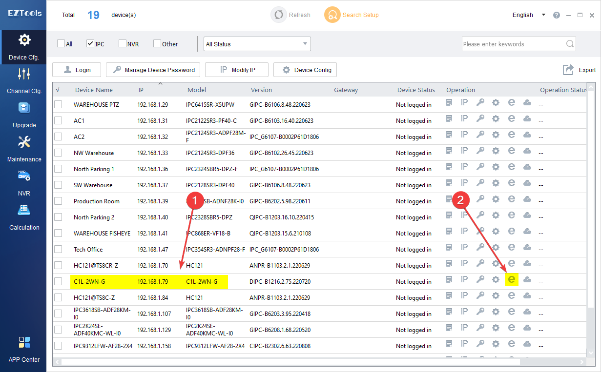
3. Open the EZTools 2.0 software, locate the device model C1L-2WN-G on the list, then access the web interface and log in (admin/123456).
(Click on any of the pictures below to view them in more detail)
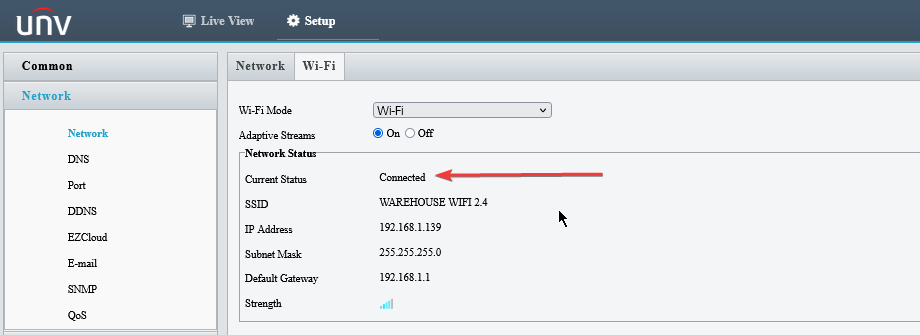
4. Go to Setup then select Network on the left menu and then click the Wi-Fi tab on the right. Next, select “Wi-Fi” from the “Wi-Fi Mode” drop down.
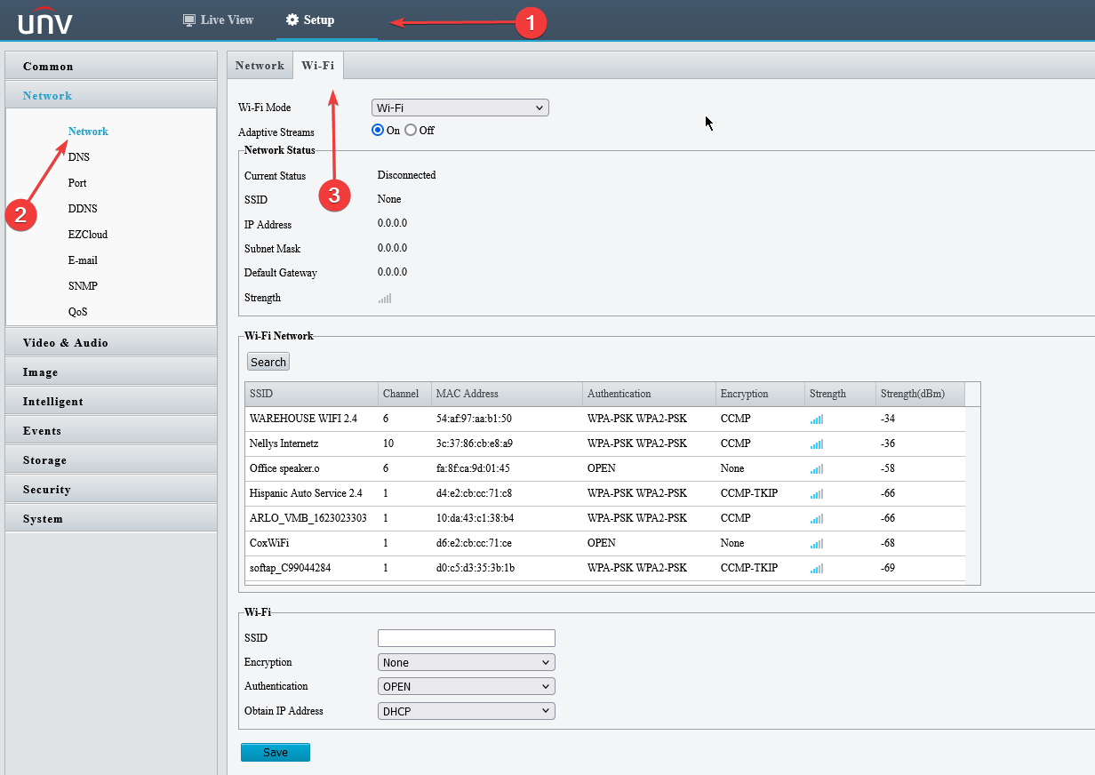
5. Click the Search button to display a list of available Wifi networks in your area. Select a wifi connection from the list by clicking on it (The SSID and Authentication fields will automatically populate). Next, type in the wifi password in the Encryption field below the list. Lastly, click the Save button.
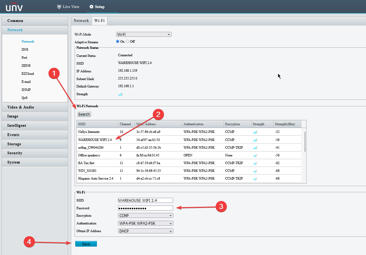
6. The cube should now be connected to the selected wifi. If everything went well “Connected” will be displayed next to the Connection Status at the top of the page.
7. You can now disconnect the ethernet cable from the router and from the Cube. After moving the Cube to it’s final location it should automatically reconnect to wifi as long as there is good signal at that location.
Advanced Uniview IP Camera Guide
Read Next :
How To Upload A Custom Audio Clip
Some select UNV models have deterrent capabilities. From that, the cameras can output a preset audio clip as a response to an event trigger.
One great feature is that UNV allows you to upload custom sounds from the EZView App!
In this guide, we are referencing the “IPC9312LFW-AF28-2X4“.
Step 1 – EZView App Configuration
From the Live View of the EZView app, click on the 3 Horizontal Lines icon in the top left corner.

Select Device Config:
Choose the camera you want to upload the audio clip to:
Select Customize Alarm Sound:
Add Alarm Sound:
Now, in the Customize Alarm Sound section, you can do either Text To Speech and choose either a Male or Female voice over, or the other option is doing an actual voice recording with the mic on your phone. Just be sure to Name the sound and hit the Save icon in the top right corner when done!
After the audio file has been saved, your sound will be listed:
Step 2 – Selecting the Custom File in Camera Interface
Now that the audio file has been set and saved, we now need to log into the camera’s interface to set it to an event linkage action.
Here is a screenshot verifying that the camera has the new audio file:
Screenshot for Trigger Action:
How To Configure Master-Slave Linkage
Master-Slave PTZ Linkage is a great functionality to utilize as you can pair a fixed camera to trigger an event and that will allow the PTZ to track the object that triggered the event.
Please Note
Only some camera models support this function. The supported linkage parameters, linkage mode and alarming schedule may vary with camera model. Please see the actual Web interface for details.
In this guide, we are referencing the Dual-Lens PTZ “IPC9312LFW-AF28-2X4“.
Step 1
From the Live View of the camera, Click Setup ->Intelligent –>Smart. Choose Master-Slave Linkage, click “⚙️” and then select Linkage Parameter tab.
Step 2
Select Enable Master-Slave Linkage.
Operating Mode on this particular model is only TrackMode.
Continuously Track or setting a Tracking Duration (In Seconds) are the options available.
After the appropriate configurations have been set, click Save.
Step 3
Select the Calibration tab.
Click Auto Calibrate -> Next -> One-Click Calibrate -> Once the Auto Calibration Finishes, Click Finish
The Camera will go through the automated process and once finished, you will then be able to utilize the Master-Slave Linkage with Smart Events!
Step 4
To utilize the Master-Slave Linkage with a Smart Event, go into a Smart Event and configure it appropriately.
Then under Trigger Actions, Select the Master-Slave Linkage option and hit Save.
In this example, we are going to be using the Line Crossing Event.
How To Setup FTP
Note
The General FTP configuration is applicable to all snapshots except face detection.
For stored snapshots taken by smart functions such as face recognition, refer to Smart FTP configuration.
General Setup
1. Click Setup > Storage > FTP. Go to General tab.
2. Set the IP address and port for the FTP server, username and password used to upload images to the FTP server, select Upload Images, Overwrite Storage and set Overwrite At (threshold for overwriting images). Some camera models support FTP test. You may test FTP after completing FTP settings correctly.
3. Set the path for saving snapshots on the FTP server and the file name format. For example, set path as Preset No.\\IP Address\\Date\\Hour(s), and set file name as Preset No.-PTZ Zoom-PTZ Latitude-PTZ Longitude.jpg.
4. Click Save.
Smart Setup
To use smart FTP, click Setup > System > Server > Intelligent Server and set Platform Communication Type to FTP.
1. Click Setup > Storage > FTP. Go to Smart tab.
2. Set the IP address and port of the FTP server, username and password used to upload images to the FTP server.
3. Set the path for saving snapshots on the FTP server and the file name format. For example, set path as Preset No.\\IP Address\\Date, and set file name as Preset No.-PTZ Latitude-PTZ Longitude-PTZ Zoom.jpg.
4. Click Save.
How To Enable PTZ Smart Tracking
Certain Uniview PTZ models support Auto Tracking. This function is used primarily to track a human in a restricted or sensitive area that is normally inaccessible.
Note
Please check the Camera’s Spec Sheet or contact technical support to verify if your model supports Auto Tracking.
Installation
- Mount Height
- 10ft – 15ft is recommended if the camera is used in restricted zones, industrial areas, or sidewalks
- 15ft is recommended for use on roads.
- Monitoring Distance
- For 4X Optical Zoom PTZs, 6ft – 80ft is recommended, and the camera works best in the range of 20ft – 30ft.
- Viewing Angle
- Top view angle range: 15°-30°.
- 20° is recommended.
- Variables
- Lighting
- Recommended: scenes with adequate and even lighting, and the camera has a clear view of the object.
- Not recommended: Camera’s view of object is blocked, and lighting is uneven.
- Object Moving Speed
- The camera may lose track of the object if the object moves faster than 17s per circle (360 degree). 15ft – 30ft monitoring distance is recommended to ensure that the object’s angular speed is not too high.
- Slanted View
- A slanted view may lead to unsatisfactory tracking performance. Adjust camera view properly by adjusting camera position or by PTZ movements.
- Unobstructed View
- The camera may stop tracking the object when the object is blocked by vehicles and tree branches. Install the camera in the center of surveillance area with an unobstructed view.
- Lens Direction
- If camera tilts down to the vertical (lens facing the ground directly) when tracking the object, the camera may not be able to keep tracking. The recommended top view angle is 15°-30° (best at 20°).
- Multiple Objects
- If multiple objects appear in the surveillance area, the camera selects and tracks the object closest to the center of the surveillance area.
- Lighting
Functionality
When the camera detects one or more human objects, it tracks the object in closest distance and makes the person in the center of the image. The camera rotates with the object’s movement.
- Continuously Track
- The camera keeps tracking the object until it disappears, and then returns to the original position.
- Max. Tracking Time
- The camera tracks the object from when the object is selected to when the tracking time is up, and then returns to the original position.
Configuration
The location of where to enable Auto Tracking may vary from PTZ to PTZ. In this guide, we are referencing the model IPC672LR-AX4DUPKC.
From the PTZ’s live view via web interface, select Setup -> Intelligent -> Smart -> Auto Tracking.
Select the Gear Icon to configure Auto Tracking.
- Max. Tracking Time
- The time (in seconds) that the camera tracks the object. The camera tracks the object for the set time duration and then returns to the original position.
- Continuously Track
- When enabled, the camera tracks the object until it disappears from the surveillance area, and then returns to the original position.
- Plan
- Set the time period for your settings to take effect.
- PTZ panel
- Control PTZ movements.
How To Fix Camera Flickering
Since most security cameras are developed outside of the United States, they’re usually set up out of the box for a 50 Hz environment. This means if you were to install your camera inside, especially in a location with fluorescent lightbulbs, you’ll likely get different results depending on where you are in the world.
If you’re outside of the US in a place where the AC standard is 50 Hz, everything will be fine. But if you are in the United States, you’ll probably start to see some horizontal bands flickering across your footage.
Adjusting Frame Rate
Log into your camera’s web interface and from the Live View, navigate to Setup -> Video&Audio -> Capture Mode to resolution at 30FPS.
Adjusting Exposure
If changing the capture mode to 30FPS does not fully help the flickering issue, then adjusting the Exposure Mode will do the trick
From the Live View page, navigate to Setup -> Image -> Image -> Exposure -> Exposure Mode set to Indoor 60Hz.
Also, for a more manual experience, setting Exposure Mode to Manual and configuring the Shutter Timing to 2 times the Frame Rate can improve the flickering as well!
How To Set Smart Illumination
Note
This function may vary with camera models. Please see actual Web interface for details
Step 1
Click Setup > Image > Image and then click Smart Illumination.
Step 2
Select the correct IR control mode and set the parameters. The following table describes
some major parameters.
- Lighting Type
- Infrared: The camera uses infrared light illumination.
- White Light: The camera uses white light illumination.
- Note – When Control Mode is set to Manual, camera can set illumination level from 0 ~ 1000
- Control Mode
- Global Mode: The camera adjusts IR illumination and exposure to achieve balanced image effects. Some areas might be overexposed if you select this option. This option is recommended if monitored range and image brightness are your first priority.
- Overexposure Restrain: The camera adjusts IR illumination and exposure to avoid regional overexposure. Some areas might be dark if you select this option. This option is recommended if clarity of the central part of the image and overexposure control are your first priority.
- Road: This mode offers strong illumination in whole and is recommended for monitoring wide-ranging scenes, for example, road.
- Park: This mode offers uniform light and is recommended for monitoring small range scenes with many obstacles, for example, industrial parks.
- Manual: This mode allows you to manually control the intensity of IR illumination.
- Indoor: This mode is recommended for application in indoor scenes
- Illumination Mode – Set the intensity level of the IR light. The greater the value, the higher the intensity. 0 means that the IR light is turned off.
- Near-illumination Level: You are recommended to set this parameter first for a wide-angle scene.
- Mid-illumination Level: You are recommended to set this parameter first if the scene requires an intermediate focal length.
- Far-illumination Level: You are recommended to set this parameter first if the scene requires a telephoto view.
- Note – You can set this parameter only when Control Mode is set to Manual.
To restore the default settings, click Default.
How To Enable Intelligent Markers
Some NVR models support Intelligent Mark. When the NVR and IP camera are both enabled, the latest areas/lines or VCA data configured for face detection, intrusion detection, and cross line detection will be displayed on the Preview, Behavior and Alarm windows in real time.
Intelligent mark is displayed on the screen as areas/lines in different colors:
Yellow – Areas/lines configured for face detection, intrusion detection, and cross line detection.
Green – VCA data has changed but not triggered rules.
Red – Rules are triggered in the configured area (rules are configured for VCA alarms), and VCA alarm has occurred.
Enabling Intelligent Markers
In this guide, we are referencing the web interface accessed via windows PC.
Once you are logged into the UNV device, go into the Setup -> Local Parameters section and Enable Intelligent Mark. Remember to hit Save!
Viewing Intelligent Markers
Once you have Intelligent Markers enabled, any active events you have will now show highlighted markers on the triggered events on the camera’s Live View.
In this example, we have Intrusion Detection enabled
Encoding Information
What Are Encoding Settings?
Encode settings are video image quality settings that are set for each camera. This menu includes the video FPS, bitrate, compression rate, and resolution. Setting these settings correctly based on the install site can help save network bandwidth, HDD space, fix network lag, and much more.
Each cameras video encode mode should be set up for every job based on how good the locations network is and how much stuff is already on it, and based off how the end user will be viewing the recorder/recordings the most.
FINDING THE VIDEO MENU
WEB BROWSER
- First open the recorder in Internet Explorer by navigating to the recorders IP address.
- Login to the recorder (Default login is Username: admin Password: 123456)
- After logging in navigate to Setup > Camera > Video (Change password now notification may
need to be closed in order to find the Setup menu)
RECORDER GUI
- Right click on the live view and select Menu
- Login to the main menu (Default login is Username: admin Password: 123456)
- After logging in Navigate to Camera > Encoding
STORAGE MODE
Storage mode is a setting that can be set for each camera individually. This allows for users to set if the
selected camera stores it mainstream to the HDD or if it stores its Sub Stream to the HDD. This can
allow users to save HDD space by letting less important cameras recorder and save at a lower quality.
IMAGE FORMAT
Image format allows for users to select the resolution and default frame rate that the cameras
mainstream will run and record at. Once the Image format is selected the “Resolution” cannot be set
differently under the Mainstream settings
MAINSTREAM
Mainstream is the highest quality stream that can be used for streaming and recording. This stream will
use the most network bandwidth and HDD space. Mainstream is normally used for recording so that
way backups always have the best quality, and for viewing cameras on the local network (if a local
computer can handle the resolution).
STREAM TYPE
Stream Type has two settings Normal and Event. Normal Encode settings are for when there is no
motion being detecting in the camera image, this is regardless of if you are recording motion or not
these Normal encode settings will need to be set. The other setting is Event Encodes these encode
settings are for when motion is being detected in the image, also for when other events are triggered
such as alarms.
Event Encodes should normally be set the same as the Normal Encode settings. In some
situations where needed or internet speeds are a issue, Normal Encode settings can be set to a very low
quality and then the Event Encodes can be set higher. This will allow for more HDD space and less
Bandwidth to be used when there is no motion or alarms going off, but customers still need 24-hour
recordings.
VIDEO COMPRESSION
Video Compression allow for users to select the type of compression that the camera will use to store
on the HDD and for viewing. The two options for compression are H.264 and H.265. H.264 is widely
supported on all industry recorders as a standard it is an older technology that can save a small amount
of bandwidth.
H.265 is the newest compression technology that can be used on Uniview 4MP cameras
and is now becoming more and more supported over the security industry. This compression rate can
save more bandwidth and HDD space than H.264 and keep a better-quality image when compressing.
RESOLUTION
Resolution is the number of pixels the camera image is displaying at. This also tells you the Mega Pixel
for example, 1920×1080 resolution is a 2MP camera and 2592×1520 is 4MP. This setting in Uniview cameras cannot be changed in the Resolution drop down this setting is changed by changing
the Image Format option.
BITRATE TYPE
Bitrate Type will be able to be set to VBR or CBR depending on the camera’s current Smart Encoding /
U-Code setting. U-Code only allows for VBR to be used this option will automatically be set if U-Code is
enabled and then be grayed out.
VBR stands for Variable Bit Rate this means the cameras streaming bit
rate will always be changing, lower bit rates when there is no motion in the image and a higher bit rate
when there is motion in the image. CBR is a constant bit rate, this setting will also stream the video at
the bitrate that is set in the Bit Rate setting.
IMAGE QUALITY
Image quality can be set to prioritize bit rate and bandwidth usage over image quality. When Bitrate
Type is set to CBR the Image Quality is always set to Highest and then grayed out. When Bitrate Type is
set to VBR the Image quality can be set to highest, higher, medium, low, lower, and lowest.
The lower the setting the lower the image quality but the less bandwidth and HDD space the camera will take
when recording / streaming.
BIT RATE
Bit Rate is how much data each camera is using in each packet that it is storing to the HDD and packet
that it is sending over the network. Bit Rate is measured in kbps so when looking at the numbers
selectable in the drop-down device by 1024 to get the Mbps that the camera is using.
IE. 1024 kbps is 1 mbps and 2048 kbps is 2 mbps. The higher Bit Rate that is set the more data that the camera
will send over the network the more bandwidth it will use. The higher the Bit Rate the mode data it will
also store on the HDD this means less recording time that can be kept. It is suggested never using more
than 4096 kbps on a jobsite with multiple camera for each camera.
FRAME RATE
Frame Rate is how many images are placed into one second of data from the camera. The higher the
frame rate the mote times the image is updated in that second. This will make the image flow a lot
smoother than a lower frame rate that has less images in one second. Frame rate will affect storage
space on the HDD, but it is very minimum at the end of the HDD space. Normally only a couple
hours will be lost in the end.
I FRAME INTERVAL
I Frame Interval is how often the background of an image is updated when there is no motion and
nothing in the background has changed. This setting is normally set up for double the FPS. IE if the
camera is set on 25 FPS the I Frame Interval will be set to 50. On cameras where there is never a lot of
motion or changes the I Frame interval can be set to 3 or 4 times the FPS.
SMOOTHING
Smoothing is another option for prioritizing bit rate over quality of the image. If the slider is set more on
the Clear side the image quality will be better and more stable but will require more bandwidth and
HDD space. If the slider is more on the Smooth side the image will be more pixelated and less stable but
require less HDD space and bandwidth.
AUDIO STREAM
Audio Stream checkboxes for on and off are to enable audio if the camera that is connected to the
channel has a microphone added to it.
SMART ENCODING
Smart Encoding has how U-Code is turned on. There are normally two options Basic and Advanced.
Basic Mode will save about 75% of bandwidth and HDD space used and will work the best when using
Uniview cameras on a 3rd party recorder. Advanced mode will save up to about 85% of bandwidth and
HDD space and will sync well with Uniview recorders.
SUB STEAM / THIRD STREAM
Sub Stream is a secondary stream on cameras that are normally set to a very low bit rate and resolution
and are used when viewing the camera remotely on a wireless data connection. This will allow for
cameras to steam a lot smoother with less lag and save data on user’s wireless plans. This feature will
also help when viewing remotely from a web browser or computer software. If the recorders location
has a slow network or upload speed viewing the camera in sub stream remotely can help get the
camera to display live video with less lag.
How To Use Power Output Function
Some IPCs support Power output function, how to configure the settings to implement this function.
Check the Camera’s Spec sheet to verify if it supports this function.
- Power the IPC through POE port.
- Enable the DV12V output function on IPC’s web interface. As the picture shown:
- Use this IPC’s external DC12V –IN port to power another IPC or microphone
How to set Edge Storage & Cache Post Recording
Edge storage is used to save video data and snapshots to the memory card directly. Edge storage is recommended when the camera is running in stand-alone mode. When the camera is managed by the central management server, you need to stop edge storage to avoid affecting the cache post recording service.
Note: Before setting, check following:
- The memory card is correctly installed on the camera.
- Backup resource has been added on the central server.
- Backup resources have been allocated for the camera.
Note: Only some certain models support these functions. Please see the actual model for details.
Note: This function and management page may vary with models. Please see the actual Web interface for details.
Edge Storage – Manual storage
- Click Setup > Storage > Storage.
- Start edge storage and modify the settings as required. The following table describes some major parameters.
- Click Save
| Parameter | Description |
| Storage Medium | Storage resource type. Note: To format the memory card, disable the storage function for the card first. Then Click Format and then click OK to confirm the operation. The system will restart when the format is completed. Information about the total and free space is displayed. |
| Data Overwrite Policy | Overwrite: If there is no free space in the memory card, new data will overwrite the existing data repeatedly.
Stop: If there is no free space in the memory card, new data will not be saved to the memory card. |
| Post-Record(s) | For alarm-triggered recording, the length of time that recording continues after the end of the alarm. |
Edge Storage – Planned storage
If planned storage is enabled, the camera records video to the memory card during the specified periods.
- Click Setup > Storage > Storage.
- Select Planned Storage, and then set the periods during which the camera records video to the memory card.
- Click Save.
Note:
-Planned storage is not effective when manual storage and planned storage are both enabled
Cache Post Recording
A camera under centralized management can use the memory card as a backup storage resource of the central management server. If storage from the camera to the central storage device is interrupted due to unstable network connection, the camera automatically will start cache post recording and store videos to the memory card.
With recording backup enabled, the camera can automatically transfer the video stored in the memory card to a storage resource of the backup server in the form of a file when the communication between the camera and the backup server is restored.
- Click Setup > Storage > Storage.
Add Comment